
BDC60-DPrüfbericht - ProdukteTest Report - Products
TUV Rheinland (Shanghai) Co., Ltd. No.177, 178, Lane 777 West Guangzhong Road, Jing'an District,Shanghai, ChinaMail: service-gc@tuv.com · Web: www.tuv.com
Test Report issued under the responsibility of: www.tuv.com Page 3 of 58 Report No.: CN23N7EK 001
Disclaimer: This document is controlled and has been released electronically. Only the version on the IECEE Website is the current document version
TRF No. IEC61851_ 1B
www.tuv.com Page 9 of 58 Report No.: CN23N7EK 001
www.tuv.com Page 12 of 58 Report No.: CN23N7EK 001
www.tuv.com Page 13 of 58 Report No.: CN23N7EK 001
www.tuv.com Page 14 of 58 Report No.: CN23N7EK 001
www.tuv.com Page 15 of 58 Report No.: CN23N7EK 001
www.tuv.com Page 16 of 58 Report No.: CN23N7EK 001
www.tuv.com Page 17 of 58 Report No.: CN23N7EK 001
www.tuv.com Page 18 of 58 Report No.: CN23N7EK 001
www.tuv.com Page 19 of 58 Report No.: CN23N7EK 001
www.tuv.com Page 20 of 58 Report No.: CN23N7EK 001
www.tuv.com Page 21 of 58 Report No.: CN23N7EK 001
www.tuv.com Page 22 of 58 Report No.: CN23N7EK 001
www.tuv.com Page 23 of 58 Report No.: CN23N7EK 001
www.tuv.com Page 24 of 58 Report No.: CN23N7EK 001
www.tuv.com Page 25 of 58 Report No.: CN23N7EK 001
www.tuv.com Page 26 of 58 Report No.: CN23N7EK 001
www.tuv.com Page 27 of 58 Report No.: CN23N7EK 001
www.tuv.com Page 28 of 58 Report No.: CN23N7EK 001
www.tuv.com Page 29 of 58 Report No.: CN23N7EK 001
www.tuv.com Page 30 of 58 Report No.: CN23N7EK 001
www.tuv.com Page 31 of 58 Report No.: CN23N7EK 001
www.tuv.com Page 32 of 58 Report No.: CN23N7EK 001
www.tuv.com Page 33 of 58 Report No.: CN23N7EK 001
www.tuv.com Page 34 of 58 Report No.: CN23N7EK 001
www.tuv.com Page 35 of 58 Report No.: CN23N7EK 001
www.tuv.com Page 36 of 58 Report No.: CN23N7EK 001
www.tuv.com Page 37 of 58 Report No.: CN23N7EK 001
www.tuv.com Page 38 of 58 Report No.: CN23N7EK 001
www.tuv.com Page 39 of 58 Report No.: CN23N7EK 001
www.tuv.com Page 40 of 58 Report No.: CN23N7EK 001
www.tuv.com Page 41 of 58 Report No.: CN23N7EK 001
www.tuv.com Page 42 of 58 Report No.: CN23N7EK 001
www.tuv.com Page 43 of 58 Report No.: CN23N7EK 001
www.tuv.com Page 44 of 58 Report No.: CN23N7EK 001
www.tuv.com Page 45 of 58 Report No.: CN23N7EK 001
www.tuv.com Page 46 of 58 Report No.: CN23N7EK 001
www.tuv.com Page 47 of 58 Report No.: CN23N7EK 001
www.tuv.com Page 48 of 58 Report No.: CN23N7EK 001
www.tuv.com Page 49 of 58 Report No.: CN23N7EK 001
www.tuv.com Page 50 of 58 Report No.: CN23N7EK 001
www.tuv.com Page 51 of 58 Report No.: CN23N7EK 001
www.tuv.com Page 52 of 58 Report No.: CN23N7EK 001
www.tuv.com Page 53 of 58 Report No.: CN23N7EK 001
www.tuv.com Page 54 of 58 Report No.: CN23N7EK 001
www.tuv.com Page 55 of 58 Report No.: CN23N7EK 001
www.tuv.com Page 56 of 58 Report No.: CN23N7EK 001
www.tuv.com Page 57 of 58 Report No.: CN23N7EK 001
www.tuv.com Page 58 of 58 Report No.: CN23N7EK 001
Test Report issued under the responsibility of: www.tuv.com Page 1 of 50 Report No. CN23N7EK 001 Attachment 1
www.tuv.com Page 4 of 50 Report No. CN23N7EK 001 Attachment 1
www.tuv.com Page 5 of 50 Report No. CN23N7EK 001 Attachment 1
www.tuv.com Page 6 of 50 Report No. CN23N7EK 001 Attachment 1
www.tuv.com Page 9 of 50 Report No.CN23N7EK 001 Attachment 1
www.tuv.com Page 10 of 50 Report No.CN23N7EK 001 Attachment 1
www.tuv.com Page 11 of 50 Report No.CN23N7EK 001 Attachment 1
www.tuv.com Page 12 of 50 Report No.CN23N7EK 001 Attachment 1
www.tuv.com Page 13 of 50 Report No.CN23N7EK 001 Attachment 1
www.tuv.com Page 14 of 50 Report No.CN23N7EK 001 Attachment 1
www.tuv.com Page 15 of 50 Report No.CN23N7EK 001 Attachment 1
www.tuv.com Page 16 of 50 Report No.CN23N7EK 001 Attachment 1
www.tuv.com Page 17 of 50 Report No.CN23N7EK 001 Attachment 1
www.tuv.com Page 18 of 50 Report No.CN23N7EK 001 Attachment 1
www.tuv.com Page 19 of 50 Report No.CN23N7EK 001 Attachment 1
www.tuv.com Page 20 of 50 Report No.CN23N7EK 001 Attachment 1
www.tuv.com Page 21 of 50 Report No.CN23N7EK 001 Attachment 1
www.tuv.com Page 22 of 50 Report No.CN23N7EK 001 Attachment 1
www.tuv.com Page 23 of 50 Report No.CN23N7EK 001 Attachment 1
www.tuv.com Page 24 of 50 Report No.CN23N7EK 001 Attachment 1
www.tuv.com Page 25 of 50 Report No.CN23N7EK 001 Attachment 1
www.tuv.com Page 26 of 50 Report No.CN23N7EK 001 Attachment 1
www.tuv.com Page 27 of 50 Report No.CN23N7EK 001 Attachment 1
www.tuv.com Page 28 of 50 Report No.CN23N7EK 001 Attachment 1
www.tuv.com Page 29 of 50 Report No.CN23N7EK 001 Attachment 1
www.tuv.com Page 30 of 50 Report No.CN23N7EK 001 Attachment 1
www.tuv.com Page 31 of 50 Report No.CN23N7EK 001 Attachment 1
www.tuv.com Page 32 of 50 Report No.CN23N7EK 001 Attachment 1
www.tuv.com Page 33 of 50 Report No.CN23N7EK 001 Attachment 1
www.tuv.com Page 34 of 50 Report No.CN23N7EK 001 Attachment 1
www.tuv.com Page 35 of 50 Report No.CN23N7EK 001 Attachment 1
www.tuv.com Page 36 of 50 Report No.CN23N7EK 001 Attachment 1
www.tuv.com Page 37 of 50 Report No.CN23N7EK 001 Attachment 1
www.tuv.com Page 38 of 50 Report No.CN23N7EK 001 Attachment 1
www.tuv.com Page 39 of 50 Report No.CN23N7EK 001 Attachment 1
www.tuv.com Page 40 of 50 Report No.CN23N7EK 001 Attachment 1
www.tuv.com Page 41 of 50 Report No.CN23N7EK 001 Attachment 1
www.tuv.com Page 42 of 50 Report No.CN23N7EK 001 Attachment 1
www.tuv.com Page 43 of 50 Report No.CN23N7EK 001 Attachment 1
www.tuv.com Page 44 of 50 Report No.CN23N7EK 001 Attachment 1
www.tuv.com Page 45 of 50 Report No.CN23N7EK 001 Attachment 1
www.tuv.com Page 46 of 50 Report No.CN23N7EK 001 Attachment 1
www.tuv.com Page 47 of 50 Report No.CN23N7EK 001 Attachment 1
www.tuv.com Page 48 of 50 Report No.CN23N7EK 001 Attachment 1
www.tuv.com Page 49 of 50 Report No.CN23N7EK 001 Attachment 1
www.tuv.com Page 50 of 50 Report No.CN23N7EK 001 Attachment 1
--End of report-- Test Report issued under the responsibility of:
Page 2 of 40 Report No. CN23N7EK 001 attachment 2
Page 3 of 40 Report No. CN23N7EK 001 attachment 2
Page 4 of 40 Report No. CN23N7EK 001 attachment 2
Page 5 of 40 Report No. CN23N7EK 001 attachment 2
Page 6 of 40 Report No. CN23N7EK 001 attachment 2
Page 7 of 40 Report No. CN23N7EK 001 attachment 2
Page 8 of 40 Report No. CN23N7EK 001 attachment 2
Page 9 of 40 Report No. CN23N7EK 001 attachment 2
Page 10 of 40 Report No. CN23N7EK 001 attachment 2
Page 11 of 40 Report No. CN23N7EK 001 attachment 2
TRF No. IEC61851_24A Page 12 of 40 Report No. CN23N7EK 001 attachment 2
Page 13 of 40 Report No. CN23N7EK 001 attachment 2
Page 14 of 40 Report No. CN23N7EK 001 attachment 2
Page 15 of 40 Report No. CN23N7EK 001 attachment 2
Page 16 of 40 Report No. CN23N7EK 001 attachment 2
Page 17 of 40 Report No. CN23N7EK 001 attachment 2
Page 18 of 40 Report No. CN23N7EK 001 attachment 2
Page 19 of 40 Report No. CN23N7EK 001 attachment 2
Page 20 of 40 Report No. CN23N7EK 001 attachment 2
Page 21 of 40 Report No. CN23N7EK 001 attachment 2
Page 22 of 40 Report No. CN23N7EK 001 attachment 2
Page 23 of 40 Report No. CN23N7EK 001 attachment 2
Page 24 of 40 Report No. CN23N7EK 001 attachment 2
Page 25 of 40 Report No. CN23N7EK 001 attachment 2
Page 26 of 40 Report No. CN23N7EK 001 attachment 2
Page 27 of 40 Report No. CN23N7EK 001 attachment 2
Page 28 of 40 Report No. CN23N7EK 001 attachment 2
Page 29 of 40 Report No. CN23N7EK 001 attachment 2
Page 30 of 40 Report No. CN23N7EK 001 attachment 2
Page 31 of 40 Report No. CN23N7EK 001 attachment 2
Page 32 of 40 Report No. CN23N7EK 001 attachment 2
Page 33 of 40 Report No. CN23N7EK 001 attachment 2
Page 34 of 40 Report No. CN23N7EK 001 attachment 2
Page 35 of 40 Report No. CN23N7EK 001 attachment 2
Page 36 of 40 Report No. CN23N7EK 001 attachment 2
Page 37 of 40 Report No. CN23N7EK 001 attachment 2
Page 38 of 40 Report No. CN23N7EK 001 attachment 2
Page 39 of 40 Report No. CN23N7EK 001 attachment 2
Page 40 of 40 Report No. CN23N7EK 001 attachment 2 List of test equipment used:A completed list of used test equipment shall be provided in the Test Reports when a Manufacturer Testing Laboratory according to CTF stage 1 or CTF stage 2 procedure has been used.Note: This page may be removed when CTF stage 1 or CTF stage 2 are not used. See also clause 4.8 in OD 2020 for more details.
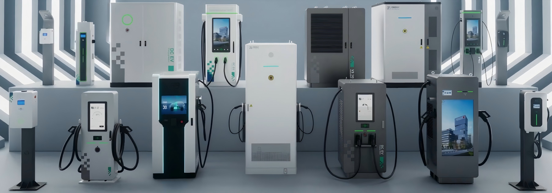
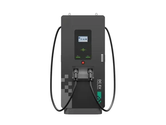
TRF No. IEC61851_24A ATTACHMENT 3 Photo Documentation Page 1 of 13 Report No.: CN23N7EK 001 Product: DC EV Charging StationType Designation: Refer to report CN23N7EK 001 Front view of unit Product:Type Designation: Photo Documentation Page 2 of 13 DC EV Charging StationRefer to report CN23N7EK 001 Report No.: CN23N7EK 001 Side view of unit,charging connector and cable Product:Type Designation: Photo Documentation Page 3 of 13 DC EV Charging StationRefer to report CN23N7EK 001 Report No.: CN23N7EK 001 AC SPD circuits Product:Type Designation: Photo Documentation Page 4 of 13 DC EV Charging StationRefer to report CN23N7EK 001 Report No.: CN23N7EK 001 AC MCCB and protective grounding busbar,conductor Product:Type Designation: Photo Documentation Page 5 of 13 DC EV Charging StationRefer to report CN23N7EK 001 Report No.: CN23N7EK 001 AC contactor DC meter Product:Type Designation: Photo Documentation Page 6 of 13 DC EV Charging StationRefer to report CN23N7EK 001 Report No.: CN23N7EK 001 Internal terminal block AC RCD circuits for AC output Photo Documentation Page 7 of 13 Product: DC EV Charging StationType Designation: Refer to report CN23N7EK 001 Report No.: CN23N7EK 001 Front view of charging module Photo Documentation Page 8 of 13 Product: DC EV Charging StationType Designation: Refer to report CN23N7EK 001 Report No.: CN23N7EK 001 Back view of charging module Product:Type Designation: Photo Documentation Page 9 of 13 DC EV Charging StationRefer to report CN23N7EK 001 Report No.: CN23N7EK 001 LED board FCR board Product:Type Designation: Photo Documentation Page 10 of 13 DC EV Charging StationRefer to report CN23N7EK 001 Report No.: CN23N7EK 001 LCD board PSU Product:Type Designation: Photo Documentation Page 11 of 13 DC EV Charging StationRefer to report CN23N7EK 001 Report No.: CN23N7EK 001 EV charging controller Communication module Product:Type Designation: Photo Documentation Page 12 of 13 DC EV Charging StationRefer to report CN23N7EK 001 Report No.: CN23N7EK 001 DC output circuits Product:Type Designation: Photo Documentation Page 13 of 13 DC EV Charging StationRefer to report CN23N7EK 001 Report No.: CN23N7EK 001 Internal DC fan --- END ---
| Prüfbericht-Nr.: Test report no.: | CN23N7EK 001 Auftrags-Nr.:Order no.: | 244457280 Seite 1 von 58 Page 1 of 58 | |||
| Kunden-Referenz-Nr.: 2055198 Auftragsdatum: 2022-12-24Client reference no.: Order date: | |||||
| Auftraggeber: Xiamen Enterprise Electric Intelligent Technology Co., Ltd.Client: Wenzhou Bridge Industrical Zone | |||||
| Prüfgegenstand: DC EV Charging StationTest item: | |||||
| Bezeichnung / Typ-Nr.: Refer to below descriptionIdentification / Type no.: | |||||
| Auftrags-Inhalt:Order content: | TÜV Bauart Mark Certificate approval | ||||
| Prüfgrundlage:Test specification: | EN IEC 61851-1: 2019,IEC 61851-1: 2017EN 61851-23: 2014,IEC 61851-23: 2014EN 61851-24: 2014,IEC 61851-24: 2014 | ||||
| Wareneingangsdatum: 2023-02-10 Date of sample receipt: | 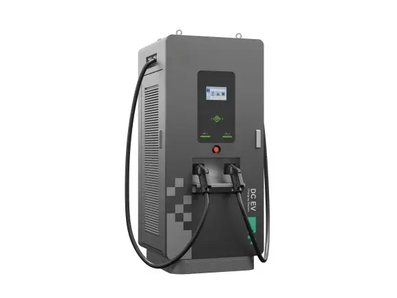 | ||||
| Prüfmuster-Nr.:Test sample no: | A003448117-001 | ||||
| Prüfzeitraum:Testing period: | 2022-02-10 - 2023-04-12 | ||||
| Ort der Prüfung:Place of testing: | TÜV Rheinland (Shanghai)Co., Ltd. | ||||
| Prüflaboratorium:Testing laboratory: | TÜV Rheinland (Shanghai)Co., Ltd. | ||||
| Prüfergebnis*:Test result*: | Pass | ||||
| geprüft von:tested by:Datum:Date: 2023-06-26Stellung / Position: | Rafer Xu Engineer | genehmigt von:authorized by:Ausstellungsdatum:Issue date: 2023-06-26 Stellung / Position: | |||
| Yue Yin Reviewer | |||||
| Sonstiges / Other: | BADCa-D(a can be 62,82,102,112,142,172,182,202,232,262),BADCb-S(b can be 52,62,82,102,112,142,172,182,202,232,262),BDCc-D(c can be 40,60,80,90,120,150,160,180,210,240),BDCd-S(d can be 30,40,60,80,90,120,150,160,180,210,240) | ||||
| Zustand des Prüfgegenstandes bei Anlieferung: Prüfmuster vollständig und unbeschädigtCondition of the test item at delivery: Test item complete and undamaged | |||||
| * Legende: P(ass) = entspricht o.g. Prüfgrundlage(n) F(ail) = entspricht nicht o.g. Prüfgrundlage(n) N/A = nicht anwendbar N/T = nicht getestet* Legend: P(ass) = passed a.m. test specification(s) F(ail) = failed a.m. test specification(s) N/A = not applicable N/T = not tested | |||||
| Dieser Prüfbericht bezieht sich nur auf das o.g. Prüfmuster und darf ohne Genehmigung der Prüfstelle nichtauszugsweise vervielfältigt werden. Dieser Bericht berechtigt nicht zur Verwendung eines Prüfzeichens.This test report only relates to the above mentioned test sample as. Without permission of the test center this test report is notes permitted to be duplicated in extracts. This test report does not entitle to carry any test mark. | |||||
| Prüfbericht-Nr.: CN23N7EK 001Test report no.: | Seite 2 von 58Page 2 of 58 | ||
| AbsatzClause | Anforderungen - Prüfungen /Requirements - Tests | Messergebnisse – Bemerkungen/Measuring results - Remarks | ErgebnisResult |
| 1 | Alle eingesetzten Prüfmittel waren zum angegebene n Prüfzeitraum gemäß eines festgelegtenKalibrierungsprogramms unseres Prüfhauses kalibriert. Sie entsprechen den in den Prüfprogrammenhinterlegten Anforderungen. Die Rückverfolgbarkeit der eingesetzten Prüfmittel ist durch die Einhaltung der Regelungen unseres Managementsystems gegeben.Detaillierte Informationen bezüglich Prüfkonditionen, Prüfequipment und Messunsicherheiten sind im Prüflabor vorhanden und können auf Wunsch bereitgestellt werden.The equipment used during the specified testing period was calibrated according to our test laboratory calibration program. The equipment fulfils the requirements included in the relevant standards. Thetraceability of the test equipment used is ensured by compliance with the regulations of our management system.Detailed information regarding test conditions, equipment and measurement uncertainty is available in the test laboratory and could be provided on request. |
| 2 | Wie vertraglich vereinbart, wurde dieses Dokument nur digital unterzeichnet. Der TÜV Rheinland hat nicht überprüft, welche rechtlichen oder sonstigen diesbezüglichen Anforderungen für dieses Dokument gelten. Diese Überprüfung liegt in der Verantwortung des Benutzers dieses Dokuments. Auf Verlangen desKunden kann der TÜV Rheinland die Gültigkeit der digitalen Signatur durch ein gesondertes Dokument bestätigen. Diese Anfrage ist an unseren Vertrieb zu richten. Eine Umweltgebühr für einen solchenzusätzlichen Service wird erhoben.As contractually agreed, this document has been signed digitally only. TUV Rheinland has not verifiedand unable to verify which legal or other pertaining requirements are applicable for this document. Such verification is within the responsibility of the user of this document. Upon request by its client, TUVRheinland can confirm the validity of the digital signature by a separate document. Such request shall be addressed to our Sales department. An environmental fee for such additional service will be charged. |
| 3 | Prüfklausel mit der Note * wurden an qualifizierte Unterauftragnehmer vergeben und sind unter der jeweiligen Prüfklausel des Berichts beschrieben.Abweichungen von Prüfspezifikation(en) oder Kundenanforderungen sind in der jeweiligen Prüfklausel im Bericht aufgeführt.Test clauses with remark of * are subcontracted to qualified subcontractors and descripted under the respective test clause in the report.Deviations of testing specification(s) or customer requirements are listed in specific test clause in the report. |
| 4 | Die Entscheidungsregel für Konformitätserklärungen basierend auf numerischen Messergebnisen indiesem Prüfbericht basiert auf der "Null-Grenzwert-Regel" und der "Einfachen Akzeptanz" gemäß ILAC G8:2019 und IEC Guide 115:2021, es sei denn, in der auf Seite 1 dieses Berichts genanntenangewandten Norm ist etwas anderes festgelegt oder vom Kunden gewünscht. Dies bedeutet, dass die Messunsicherheit nicht berücksichtigt wird und daher auch nicht im Prüfbericht angegeben wird. Zuweiteren Informationen bezueglich des Risikos durch diese Entscheidungsregel siehe ILAC G8:2019.The decision rule for statements of conformity, based on numerical measurement results, in this testreport is based on the “Zero Guard Band Rule” and “Simple Acceptance” in accordance with ILACG8:2019 and IEC Guide 115:2021, unless otherwise specified in the applied standard mentioned on Page 1 of this report or requested by the customer. This means that measurement uncertainty is not taken inaccount and hence also not declared in the test report. For additional information to the resulting risk based of this decision rule please refer to ILAC G8:2019. |
| TEST REPORTIEC 61851-1: 2017Electric vehicle conductive charging systemPart 1: General requirements | |
| Report Number : CN23N7EK 001Date of issue : See cover pageTotal number of pages : See cover page | |
| Name of Testing Laboratory TÜV Rheinland (Shanghai) Co., Ltd. | |
| Applicant’s name : Xiamen Enterprise Electric Intelligent Technology Co., Ltd.Address ........................................... : Wenzhou Bridge IndustricalZone,Beibaixiang | |
| Test specification:Standard : IEC 61851-1:2017Test procedure : TÜV Bauart Mark Certificate approvalNon-standard test method : N/A | |
| Test Report Form No : IEC61851_1BTest Report Form(s) Originator : VDE Prüf- und Zertifizierungsinstitut GmbHMaster TRF : Dated 2018-02- 19Copyright © 2018 IEC System of Conformity Assessment Schemes for Electrotechnical Equipment and Components (IECEE System). All rights reserved.This publication may be reproduced in whole or in part for non-commercial purposes as long as the IECEE is acknowledged as copyright owner and source of the material. IECEE takes no responsibility for and will not assume liability for damages resulting from the reader's interpretation of the reproduced material due to its placement and context.If this Test Report Form is used by non-IECEE members, the IECEE/IEC logo and the reference to the CB Scheme procedure shall be removed.This report is not valid as a CB Test Report unless signed by an approved CB Testing Laboratory and appended to a CB Test Certificate issued by an NCB in accordance with IECEE 02. | |
| General disclaimer:The test results presented in this report relate only to the object tested.This report shall not be reproduced, except in full, without the written approval of the Issuing CB Testing Laboratory. The authenticity of this Test Report and its contents can be verified by contacting the NCB, responsible for this Test Report. | |
| Test item description ....................... : Trade Mark : Manufacturer : Model/Type reference ...................... : Ratings .............................................. : | DC EV Charging Station Same as applicantBDC60-DSee copy of marking label and model list. | |||
| Responsible Testing Laboratory (as applicable), testing procedure and testing location(s): N/A | ||||
| CB Testing Laboratory: | ||||
| Testing location/ address............................. : | ||||
| Tested by (name, function, signature) ........ : | ||||
| Approved by (name, function, signature) ... : | ||||
| Testing procedure: CTF Stage 1: | ||||
| Testing location/ address............................. : | ||||
| Tested by (name, function, signature) ........ : | ||||
| Approved by (name, function, signature) ... : | ||||
| Testing procedure: CTF Stage 2: | ||||
| Testing location/ address............................. : | ||||
| Tested by (name + signature) ...................... : | ||||
| Witnessed by (name, function, signature) . : | ||||
| Approved by (name, function, signature) ... : | ||||
| Testing procedure: CTF Stage 3: | ||||
| Testing procedure: CTF Stage 4: | ||||
| Testing location/ address............................. : | ||||
| Tested by (name, function, signature) ........ : | ||||
| Witnessed by (name, function, signature) . : | ||||
| Approved by (name, function, signature) ... : | ||||
| Supervised by (name, function, signature) : | ||||
| List of Attachments (including a total number of pages in each attachment): Attachment 1: Test report of EN 61851-23:2014 (Total 50 pages)Attachment 2: Test report of EN 61851-24:2014 (Total 40 pages)Attachment 3: Photo Document (Total 13 pages) | |
| Summary of testing: | |
| Tests performed (name of test and test clause):6.3 Functions provided in Mode 2, 3 and 48.2.2 Loss of supply voltage to permanently connected EV supply equipment12.2.6 Inrush current12.3 Clearances and creepage distances12.4 IP degrees12.5 Insulation resistance12.6 Touch current12.7.1 AC withstand voltage12.7.2 Impulse dielectric withstand test12.8 Temperature rise12.9 Damp heat functional test12.10 Minimum temperature functional test16.5 Durability test for marking Material testANNEX A Control pilot function through a control pilot circuit using a PWM signal and a control pilot wire | Testing location: TÜV Rheinland (Shanghai) Co. Ltd.No.177, 178, Lane 777 West Guangzhong Road, Jing'an District, Shanghai, China. |
| Summary of compliance with National Differences (List of countries addressed): No EU Group Differences The product fulfils the requirements of EN IEC 61851-1:2019,IEC 61851-1:2017. | |
| IEC 61851-1 | |||
| Clause | Requirement + Test | Result - Remark | Verdict |
| Test item particulars...................................................: |
| Equipment mobility .......................................................: 口 movable 口 hand-held 口 transportable stationary 口 for building-in 口 direct plug-inConnection to the mains ...............................................: 口 pluggable equipment 口 type A 口 type B permanent connection口 detachable power supply cord口 non-detachable power supply cord口 not directly connected to the mainsEV charging modes ......................................................: 口 Mode 1 charging口 Mode 2 chargingMode 3 chargingMode 4 chargingType of EV connection .................................................: Case A口 Case BCase CAccess location ............................................................: operator accessible口 service access area口 restricted access locationOver voltage category (OVC) ......................................: 口 OVC I 口 OVC II OVC III 口 OVC IV口 other:Mains supply tolerance (%) or absolute mains supply ±10%values :Tested for IT power systems : Yes NoIT testing, phase-phase voltage (V) : N/AClass of equipment : Class I Class II Class IIINot classifiedConsidered current rating (A) : Refer to model listPollution degree (PD) : PD 1 PD 2(inside) PD 3(outside)IP protection class : IP55Altitude during operation (m) : ≤2000Altitude of test laboratory (m) : <500Mass of equipment (kg) : Refer to model list |
| Possible test case verdicts:- test case does not apply to the test object ........... : N/A- test object does meet the requirement.................. : P (Pass)- test object does not meet the requirement........... : F (Fail) |
| IEC 61851-1 | |||
| Clause | Requirement + Test | Result - Remark | Verdict |
| Testing.......................................................................... :Date of receipt of test item ........................................ : See cover page Date (s) of performance of tests ............................... : See cover page | |
| General remarks: | |
| "(See Enclosure #)" refers to additional information appended to the report."(See appended table)" refers to a table appended to the report. Throughout this report a 口 comma / 区 point is used as the decimal separator. | |
| Manufacturer’s Declaration per sub-clause 4.2.5 of IECEE 02: | |
| The application for obtaining a CB Test Certificateincludes more than one factory location and adeclaration from the Manufacturer stating that thesample(s) submitted for evaluation is (are)representative of the products from each factory has been provided ............................................................... : | 口 Yes Not applicable |
| When differences exist; they shall be identified in the General product information section. | |
| Name and address of factory (ies) .......................... : Same as applicant | |
| IEC 61851-1 | |||
| Clause | Requirement + Test | Result - Remark | Verdict |
| General product information and other remarks:This charging station combined AC Type 2 and DC CCS2 output connector, it may has two DC CCS2 connectors and one AC Type 2 connector.There are four operation configurations described as below:1. When there is only one connector, it can work with one DC CCS 2 connector, the maximum power is 240kW.2. When two DC CCS 2 connectors work together, the maximum power of each connector is 120kW, the total maximum capability is 240kW.3. When one DC CCS 2 connector work together AC Type 2 connector, the maximum power of DC CCS2 connector is 240kW and 22kW for AC Type 2,the total maximum capability is 262kW.4. When two DC CCS 2 connectors work together AC Type 2 connector, the maximum power of DC CCS2 connector is 120kW max per connector and 22kW for AC Type 2,the total maximum capability is 262kW. The charging station has two different colour of enclosure,one is white and another is black.For the aspect of Residual Current Protection, this EVSE is installed internal circuit breaker combine with Type A RCD for DC part and Type B RCD for AC part which are certified.System diagram |
| IEC 61851-1 | |||
| Clause | Requirement + Test | Result - Remark | Verdict |
| IEC 61851-1 | |||
| Clause | Requirement + Test | Result - Remark | Verdict |
| Output power curve: |
| IEC 61851-1 | |||
| Clause | Requirement + Test | Result - Remark | Verdict |
Model list:
|
| IEC 61851-1 | |||
| Clause | Requirement + Test | Result - Remark | Verdict |
| CCS2:DC 150-1000V ,200A max ,60KWType2:AC 400V ,32A max ,22KW | ||||
| BADC82-S | 400Vac±10% ,139A | CCS2:DC 150-1000V ,200A max ,60KWType2:AC 400V ,32A max ,22KW | 329 | |
| BADC62-D | 400Vac±10% ,105A | CCS2:DC 150-1000V ,133A max ,40KWCCS2:DC 150-1000V ,133A max ,40KWType2:AC 400V ,32A max ,22KW | 336 | |
| BADC62-S | 400Vac±10% ,105A | CCS2:DC 150-1000V ,133A max ,40KWType2:AC 400V ,32A max ,22KW | 321 | |
| BADC52-S | 400Vac±10% ,88A | CCS2:DC 150-1000V ,100A max ,30KWType2:AC 400V ,32A max ,22KW | 314 | |
| BDC240-D | 400Vac±10% ,406A | CCS2:DC 150-1000V ,250A max ,240KWCCS2:DC 150-1000V ,250A max ,240KW | 424.5 | |
| BDC240-S | 400Vac±10% ,406A | CCS2:DC 150-1000V ,250A max ,240KW | 409.5 | |
| BDC210-D | 400Vac±10% ,355A | CCS2:DC 150-1000V ,250A max ,210KWCCS2:DC 150-1000V ,250A max ,210KW | 409.5 | |
| BDC210-S | 400Vac±10% ,355A | CCS2:DC 150-1000V ,250A max ,210KW | 394.5 | |
| BDC180-D | 400Vac±10% ,304A | CCS2:DC 150-1000V ,250A max ,180KWCCS2:DC 150-1000V ,250A max ,180KW | 394.5 | |
| BDC180-S | 400Vac±10% ,304A | CCS2:DC 150-1000V ,250A max ,180KW | 379.5 | |
| BDC160-D | 400Vac±10% ,254A | CCS2:DC 150-1000V ,250A max ,160KWCCS2:DC 150-1000V ,250A max ,160KW | 379.5 | |
| BDC160-S | 400Vac±10% ,254A | CCS2:DC 150-1000V ,250A max ,160KW | 364.5 | |
| BDC150-D | 400Vac±10% ,254A | CCS2:DC 150-1000V ,250A max ,150KWCCS2:DC 150-1000V ,250A max ,150KW | 379.5 | |
| BDC150-S | 400Vac±10% ,254A | CCS2:DC 150-1000V ,250A max ,150KW | 364.5 | |
| BDC120-D | 400Vac±10% ,203A | CCS2:DC 150-1000V ,200A max ,120KWCCS2:DC 150-1000V ,200A max ,120KW | 364.5 | |
| BDC120-S | 400Vac±10% ,203A | CCS2:DC 150-1000V ,200A max ,120KW | 349.5 | |
| BDC90-D | 400Vac±10% ,152A | CCS2:DC 150-1000V ,200A max ,90KWCCS2:DC 150-1000V ,200A max ,90KW | 349.5 | |
| BDC90-S | 400Vac±10% ,152A | CCS2:DC 150-1000V ,200A max ,90KW | 334.5 | |
| BDC80-D | 400Vac±10% ,136A | CCS2:DC 150-1000V ,200A max ,80KWCCS2:DC 150-1000V ,200A max ,80KW | 334.5 | |
| BDC80-S | 400Vac±10% ,136A | CCS2:DC 150-1000V ,200A max ,80KW | 319.5 | |
| BDC60-D | 400Vac±10% ,102A | CCS2:DC 150-1000V ,200A max ,60KWCCS2:DC 150-1000V ,200A max ,60KW | 334.5 | |
| BDC60-S | 400Vac±10% ,102A | CCS2:DC 150-1000V ,200A max ,60KW | 319.5 | |
| BDC40-D | 400Vac±10% ,68A | CCS2:DC 150-1000V ,133A max ,40KWCCS2:DC 150-1000V ,133A max ,40KW | 311.5 | |
| BDC40-S | 400Vac±10% ,68A | CCS2:DC 150-1000V ,133A max ,40KW | 296.5 | |
| BDC30-S | 400Vac±10% ,51A | CCS2:DC 150-1000V ,100A max ,30KWCCS2:DC 150-1000V ,100A max ,30KW | 319.5 | |
| IEC 61851-1 | |||
| Clause | Requirement + Test | Result - Remark | Verdict |
| Input parameter : Refer to page 17 to 18Output parameter : Refer to page 17 to 18Protection Class : 因 I 口 II 口 IIISupply Connection : fixed power cordpermanent connection口 appliance inlet口 direct plug in口 battery operatedPlease tick above box when applicable` | |||||
| Classification of Use | indoor outdoor | ||||
| Output connector interface type | CCS2,Type 2 | ||||
| Power Supply system | TN-S 区 TN-C 区 TN-C-S 囚 TT 口 IT | ||||
| Number of Phase | Single-phase 区 | Three-phase | |||
| EV charging mode | Mode 4,Mode 3 | ||||
| EV Connection type | Case C, Type 2 | ||||
| IP Code | IP55 | ||||
| Pollution degree | PD 3(Outside), PD 2(Inside) | ||||
| Overvoltage category | OVC III | ||||
| Ambient Temperature (operating) | -30°C to +50ºC | ||||
| Ambient Temperature (Storage) | -30°C to +85ºC | ||||
| Altitude (m) | ≤2000 | ||||
| Other specific environmental conditions | N/A | ||||
| Overall dimensions(mm*mm*mm) | 800*800*1800(L*W*H) | ||||
| Mass(kg) | Refer to model list | ||||
| RCD type | External required | Type A mA 口 Type B mA | |||
| Built-in | Type A 30mA for DC charging circuitsType B 30mA for AC charging circuits | ||||
| Other functions | |||||
| IEC 61851-1 | |||
| Clause | Requirement + Test | Result - Remark | Verdict |
| 4 | GENERAL REQUIREMENTS | P | |
| The EV supply equipment shall be so constructed that an EV can be connected to the EV supplyequipment so that in normal conditions of use, the energy transfer operates safely, and itsperformance is reliable and minimises the risk of danger to the user or surroundings. | P | ||
| Unless otherwise stated all tests indicated in this document are type tests. | P | ||
| Unless otherwise stated, all tests required by this standard may be conducted on separate samples. | P | ||
| Unless otherwise stated, each test is conducted once. | P | ||
| Unless otherwise specified, all tests shall be carried out in a draught-free location and at an ambient temperature of 20°± 5 °C. | P | ||
| The EV supply equipment shall be rated for one or more of standard nominal voltages andfrequencies as given in IEC 60038. | 400Va.c.±10% 50/60Hz | P | |
| Assemblies for EV supply equipment shall comply with IEC TS 61439-7 with the exceptions oradditions as indicated in Clause 13. | P | ||
| The standard applies to equipment that isdesigned to be used at an altitude up to 2 000 m . | P | ||
| For equipment designed to be used at altitudes above 2 000 m, it is necessary to take intoaccount the reduction of the dielectric strength and the cooling effect of the air. | ≤2000m | N/A | |
| 5 | CLASSIFICATION | P | |
| 5.1.1 | Characteristics of power supply input | P | |
| The EV supply equipment shall be classified according to the supply network system that it is intended to be connected to: | P | ||
| – EV supply equipment connected to AC supply network; | P | ||
| – EV supply equipment connected to DC supply network. | N/A | ||
| The EV supply equipment shall be classified according to the electric connection method: | P | ||
| – Plug and cable connected; | N/A | ||
| – Permanently connected. | P | ||
| IEC 61851-1 | |||
| Clause | Requirement + Test | Result - Remark | Verdict |
| 5.1.2 | Characteristics of power supply output | P | |
| The EV supply equipment shall be classified according to the type of current the EV supply equipment delivers: | P | ||
| – AC EV supply equipment; | N/A | ||
| – DC EV supply equipment; | N/A | ||
| – AC and/or DC EV supply equipment. | P | ||
| 5.2 | Normal environmental conditions | P | |
| The EV supply equipment shall be classified according to the environmental conditions and use: | P | ||
| – indoor use; | P | ||
| – outdoor use. | P | ||
| 5.3 | Special environmental conditions | P | |
| The EV supply equipment may be classifiedaccording to their suitability for use in special environmental conditions other than thosespecified in this document, if declared so by the manufacturer. | P | ||
| 5.4 | Access | P | |
| The EV supply equipment shall be classified according to the location they are intended for: | P | ||
| – equipment for locations with restricted access; | N/A | ||
| – equipment for locations with non-restricted access. | P | ||
| 5.5 | Mounting method | P | |
| The EV supply equipment shall be classified according to the type of mounting: | P | ||
| a) stationary equipment; | P | ||
| – mounted on walls, poles or equivalent positions: | N/A | ||
| •flush mounted; | N/A | ||
| •surface mounted. | N/A | ||
| – pole/column/pipe-mounted | N/A | ||
| – floor mounted | P | ||
| – ground mounted. | P | ||
| b) non stationary equipment | N/A | ||
| – portable equipment; | N/A | ||
| – mobile equipment. | N/A | ||
| 5.6 | Protection against electric shock | P | |
| IEC 61851-1 | |||
| Clause | Requirement + Test | Result - Remark | Verdict |
| The equipment shall be classified according to the protection against electric shock: | P | ||
| – class I equipment; | P | ||
| – class II equipment; | N/A | ||
| – class III equipment. | N/A | ||
| 5.7 | Charging modes | P | |
| The EV supply equipment shall be classified according to 6.2: | P | ||
| Mode 1, Mode 2, Mode 3 or Mode 4 | Mode 3 and Mode 4 | P | |
| 6 | CHARGING MODES AND FUNCTIONS | P | |
| 6.1 | General | P | |
| Clause 6 describes the different charging modes and functions for energy transfer to EVs. | P | ||
| 6.2 | Charging Modes | P | |
| 6.2.1 | Mode 1 | N/A | |
| Mode 1 is a method for the connection of an EV to a standard socket-outlet of an AC supply network, utilizing a cable and plug, both of which are notfitted with any supplementary pilot or auxiliary contacts. | N/A | ||
| The rated values for current and voltage shall not exceed: | N/A | ||
| – 16 A and 250 V AC, single-phase, | N/A | ||
| – 16 A and 480 V AC, three-phase. | N/A | ||
| EV supply equipment intended for Mode 1charging shall provide a protective earthingconductor from the standard plug to the vehicleconnector. | N/A | ||
| 6.2.2 | Mode 2 | N/A | |
| Mode 2 is a method for the connection of an EV to a standard socket-outlet of an AC supply network utilizing an AC EV supply equipment with a cable and plug, with a control pilot function and system for personal protection against electric shockplaced between the standard plug and the EV. | N/A | ||
| The rated values for current and voltage shall not exceed: | N/A | ||
| – 32 A and 250 V AC single-phase; | N/A | ||
| – 32 A and 480 V AC three-phase. | N/A | ||
| Current limitations are also subject to the standard socket-outlet ratings described in 9.2. | N/A | ||
| IEC 61851-1 | |||
| Clause | Requirement + Test | Result - Remark | Verdict |
| EV supply equipment intended for Mode 2charging shall provide a protective earthingconductor from the standard plug to the vehicleconnector. | N/A | ||
| Mode 2 equipment that is destined to be mounted on a wall but is detachable by the user, or to beused in a shock resistant enclosure shall useprotection equipment as required by IEC 62752. | N/A | ||
| 6.2.3 | Mode 3 | P | |
| Mode 3 is a method for the connection of an EV to an AC EV supply equipment permanentlyconnected to an AC supply network, with a control pilot function that extends from the AC EV supply equipment to the EV. | P | ||
| EV supply equipment intended for Mode 3charging shall provide a protective earthingconductor to the EV socket-outlet and/or to the vehicle connector. | P | ||
| 6.2.4 | Mode 4 | P | |
| Mode 4 is a method for the connection of an EV to an AC or DC supply network utilizing a DCEV supply equipment, with a control pilot function that extends from the DC EV supply equipment to the EV. | P | ||
| Mode 4 equipment may be either permanently connected or connected by a cable and plug to the supply network. | P | ||
| EV supply equipment intended for Mode 4charging shall provide a protective earthingconductor or protective conductor to the vehicleconnector. | P | ||
| 6.3 | Functions provided in Mode 2, 3 and 4 | P | |
| 6.3.1 | Mandatory functions in Modes 2, 3, and 4 | P | |
| 6.3.1.1 | General | P | |
| The following control pilot functions shall be provided by the EV supply equipment: | P | ||
| •Continuous continuity checking of the protective conductor according to 6.3.1.2; | P | ||
| •Verification that the EV is properly connected to the EV supply equipment according to 6.3.1.3; | P | ||
| •Energization of the power supply to the EV according to 6.3.1.4; | P | ||
| •De-energization of the power supply to the EV according to 6.3.1.5; | P | ||
| IEC 61851-1 | |||
| Clause | Requirement + Test | Result - Remark | Verdict |
| •Maximum allowable current according to 6.3.1.6. | P | ||
| If EV supply equipment can supply more than one vehicle simultaneously, it shall ensure that thecontrol pilot function performs the above functions independently at each connecting point. | P | ||
| EV supply equipment designed for Mode 2 or Mode 3, using the control pilot conductor and utilizing accessories according to IEC 62196-2, shall be provided with control pilot functionaccording to Annex A. | P | ||
| 6.3.1.2 | Continuous continuity checking of the protective conductor | P | |
| While charging in Mode 2, the electrical continuity of the protective earthing conductor between the ICCB and the respective EV contact shall becontinuously monitored by the ICCB. | N/A | ||
| While charging in Mode 3, the electrical continuity of the protective earthing conductor between the EV charging station and the respective EV contact shall be continuously monitored by the EV supply equipment. | P | ||
| While charging in Mode 4, the electrical continuity of the protective conductor between the EVcharging station and the respective EV contactshall be continuously monitored by the EV supply equipment. | P | ||
| The EV supply equipment shall disconnect the supply to the EV in case of: | P | ||
| •loss of electrical continuity of the protective conductor (i.e. open control pilot circuit), within 100 ms. | P | ||
| •incapacity to verify the continuity of the protective conductor (e.g. short circuit between pilot wire and protective conductor), within 3 s. | P | ||
| 6.3.1.3 | Verification that the EV is properly connected to the EV supply equipment | P | |
| The EV supply equipment shall be able todetermine that the EV is properly connected to the EV supply equipment. | P | ||
| 6.3.1.4 | Energization of the power supply to the EV | P |
| IEC 61851-1 | |||
| Clause | Requirement + Test | Result - Remark | Verdict |
| The EV socket-outlet or the vehicle connectorshall not be energized unless the control pilotfunction between EV supply equipment and EV has been established correctly with signal states allowing energization. | P | ||
| The presence of such states does not imply that energy will be transferred between the EV supply equipment and the EV as this may be subject to other external conditions, e.g. energymanagement system . | P | ||
| If the EV requests ventilation, the EV supplyequipment shall only energize the system if such ventilation is provided by the installation or thepremises. | With the ventilationequipment inside the EVSE | P | |
| 6.3.1.5 | De-energization of the power supply to the EV | P | |
| If the control pilot signal is interrupted the power supply to the EV shall be interrupted according to 6.3.1.2. | EVSE stop charging while CP signal been interrupted. | P | |
| If the control pilot signal status no longer allows energization, the power supply to the EV shall be interrupted but the control pilot signalling mayremain in operation. | P | ||
| 6.3.1.6 | Maximum allowable current | P | |
| A means shall be provided to inform the EV of the value of the maximum current it is allowed to draw. The value of the maximum current permitted shall betransmitted and shall not exceed any of the following: | P | ||
| •the rated output current of the EV supply equipment, | P | ||
| •the rated current of the cable assembly. | P | ||
| The transmitted value may change, withoutexceeding the maximum allowed current, to adapt to power limitations, e.g. for load management. | P | ||
| The EV supply equipment may interrupt the energy supply if the current drawn by the EV exceeds the transmitted value. | P | ||
| 6.3.2 | Optional functions for Modes 2, 3 and 4 | P | |
| 6.3.2.1 | General | P | |
| The optional functions that are implemented shall be indicated in the manual and shall fulfil therequirements of 6.3.2. | P | ||
| 6.3.2.2 | Ventilation during supply of energy | P | |
| IEC 61851-1 | |||
| Clause | Requirement + Test | Result - Remark | Verdict |
| EV supply equipment can exchange information with installation regarding the request andpresence for ventilation. | P | ||
| 6.3.2.3 | Intentional and unintentional disconnection of the vehicle connector and/or the EV plug | P | |
| A mechanical or electromechanical means shall be provided to prevent intentional andunintentional disconnection under load of the vehicle connector and/or plug according to IEC 62196-1. | P | ||
| 6.3.2.4 | Mode 4 using the combined charging system | N/A | |
| The combined charging system as described in Annex CC of IEC 61851-23:2014 and ISO 17409 shall be so designed that: | N/A | ||
| •AC chargeable EVs with a basic vehicle inlet do not require any means to protect the EV against DC voltage at the inlet. | N/A | ||
| •AC EV supply equipment does not require any means to be self-protected against DC voltage coming from the EV. | N/A | ||
| For DC charging, digital communication shall be established between the vehicle and the DC EV charging station that validates the DC energytransfer. | N/A | ||
| The DC supply to the vehicle shall not beconnected until such complete validation from the vehicle is achieved. | N/A | ||
| A combined interface extends the use of a basic interface for AC and DC charging. | N/A | ||
| DC charging can be achieved by using separateand additional DC power contacts to supply DCenergy to the EV or by using power contactsplaced at the position of the AC power contacts of a basic interface, if the vehicle connector and the vehicle inlet are both suitable for DC. | N/A | ||
| The basic portion of the combined vehicle inlet can be used with a basic connector for ACcharging only or with a combined connectorhaving separate contacts for AC or DC charging. | N/A | ||
| AC and DC power transfer shall not occur through the combined interface at the same time. | N/A | ||
| IEC 61851-1 | |||
| Clause | Requirement + Test | Result - Remark | Verdict |
| Analysis and design of the EV supply equipment using a basic interface for DC shall apply a risk analysis according to IEC 61508 (all parts)applying a severity level of at least S2 for the function preventing the risk of unintended DC voltage output. | N/A | ||
| 7 | COMMUNICATIONS | P | |
| 7.1 | Digital communication between the EV supply equipment and the EV | P | |
| Digital communication is optional for Modes 1, 2 and 3 | P | ||
| For Mode 4 the digital communication asdescribed in IEC 61851-24 shall be provided to allow the EV to control the EV supply equipment. | P | ||
| 7.2 | Digital communication between the EV supply equipment and the management system | N/A | |
| Telecommunication network or telecommunication port of the EV supply equipment, connected to the telecommunication network, if any, shall complywith the requirements for connection totelecommunication networks according to Clause 6 of IEC 60950-1:2005. | Not considered | N/A | |
| 8 | PROTECTION AGAINST ELECTRIC SHOCK | P | |
| 8.1 | Degrees of protection against access to hazardous-live-parts | P | |
| The different parts of the EV supply equipment as mentioned shall fulfil the following requirements: | P | ||
| •IP ratings for enclosures shall be at least IPXXC; | P | ||
| •vehicle connector when mated with vehicle inlet: IPXXD; | P | ||
| •plug mated with socket-outlet: IPXXD; | N/A | ||
| •vehicle connector intended for Mode 1 use, not mated: IPXXD; | N/A | ||
| •vehicle connector intended for Mode 2 use, not mated: IPXXB and fulfilling the following: | N/A | ||
| Minimum opening of the contact equal to theclearance according to IEC 60664-1 considering overvoltage category 2 (e.g. the value given in IEC 60664-1 for 230 V/400 V is 2,5 kV ratedimpulse voltage withstand that implies 1,5 mm separation of contacts) and inhibits the charging and warns the user in case of welded contact. | N/A | ||
| IEC 61851-1 | |||
| Clause | Requirement + Test | Result - Remark | Verdict |
| •vehicle connector and EV socket-outlet intended for Mode 3 use, not mated: IPXXB provided it is associated directly upstream with a mechanical switching device (see also 12.3) and fulfilling one of the following: | P | ||
| a) minimum opening of the contact equal to the clearance according to IEC 60664-1 considering overvoltage category 3 (e.g. the value given in IEC 60664-1 for 230 V/400 V is 4 kV ratedimpulse voltage withstand that implies at least 3 mm separation of contacts); | >3mm | P | |
| b) presence of monitoring of the switchingcontacts associated with a means to operateanother mechanical switching device providingisolating function upstream the above in case of fault of operation of the switching device upstream the accessory; | P | ||
| c) presence of shutters on live entry hole of the socket-outlets or connectors for case C. | P | ||
| 8.2 | Stored energy | P | |
| 8.2.1 | Disconnection of plug connected EV supply equipment | N/A | |
| For plug connected EV supply equipment, where the connection pins are accessible afterunplugging, one second after disconnecting the standard plug from the standard socket-outlet, the voltage between any combination of accessible contacts of the standard plug shall be less than or equal to 60 V DC or the stored charge available shall be less than 50 μC. | N/A | ||
| 8.2.2 | Loss of supply voltage to permanently connected EV supply equipment | P | |
| The voltage between power lines or power linesand protective earthing conductor, whenmeasured at the input supply terminals of the EV supply equipment, shall be less than or equal to60 V DC or the stored energy shall be less than or equal to 0,2 J within 5 seconds after disconnecting the power supply voltage to the EV supplyequipment. | Voltage decrease to zero within 1s. | P | |
| 8.3 | Fault protection | P | |
| Fault protection shall consist of one or more protective measures as permitted according to IEC 60364-4-41: | P | ||
| •automatic disconnection of supply; | MCCB for DC mode and RCD for AC mode | P | |
| •double or reinforced insulation; | P | ||
| IEC 61851-1 | |||
| Clause | Requirement + Test | Result - Remark | Verdict |
| •electrical separation if limited to the supply of one item of current-using equipment; | N/A | ||
| •extra low-voltage (SELV and PELV). | P | ||
| Electric separation is fulfilled if there is one electrically separated circuit for each EV. | P | ||
| 8.4 | Protective conductor | P | |
| The protective earthing conductor and theprotective conductor shall be of sufficient rating in accordance with requirements of IEC TS 61439-7. | P | ||
| For Modes 1, 2 and 3, a protective earthingconductor shall be provided between the ACsupply input earthing terminal of the EV supply equipment and the EV. | P | ||
| Mode 4 EV supply equipment shall provide either: | P | ||
| a) a protective earthing conductor from the input earthing terminal of the AC supply network to the EV or | P | ||
| b) a protective conductor from the EV supplyequipment to the EV if fault protection is based on electric separation. | N/A | ||
| For Modes 3 and 4 permanently connected EV supply equipment, protective earthing conductors shall not be switched. | P | ||
| 8.5 | Residual current protective devices | P | |
| EV supply equipment can have one or more connecting points to supply energy to EVs. | P | ||
| Where connecting points can be usedsimultaneously and are connected to a commoninput terminal of the EV supply equipment, they shall have individual protection incorporated in the EV supply equipment. | P | ||
| If the EV supply equipment has more than one connecting point that cannot be usedsimultaneously then such connecting points can have common protection devices. | P | ||
| EV supply equipment that includes an RCD and that does not use the protective measure of electrical separation shall comply with the following: | N/A | ||
| •The connecting point of the EV supply equipment shall be protected by an RCD having a ratedresidual operating current not exceeding 30 mA; | N/A | ||
| •RCD(s) protecting connecting points shall be at least type A; | N/A | ||
| IEC 61851-1 | |||
| Clause | Requirement + Test | Result - Remark | Verdict |
| •RCDs shall comply with one of the followingstandards: IEC 61008-1, IEC 61009-1, IEC 60947- 2 and IEC 62423; | N/A | ||
| •RCDs shall disconnect all live conductors. | N/A | ||
| Where the EV supply equipment is equipped with a socket-outlet or vehicleconnector for AC use in accordance with IEC 62196 (all parts), protectivemeasures against DC fault current shall be taken. The appropriate measures shall be: | P | ||
| •RCD type B or | Type B RCD | P | |
| •RCD Type A and appropriate equipment thatensures the disconnection of the supply in case of DC fault current above 6 mA. | N/A | ||
| 8.6 | Safety requirements for signalling circuits between the EV supply equipment and the EV | P | |
| Any circuit for signalling, which extends beyondthe EV supply equipment enclosure for connection with the EV (e.g. control pilot circuit), shall beextra low voltage (SELV or PELV) according to IEC 60364-4-41. | P | ||
| 8.7 | Isolating transformers | N/A | |
| Isolating transformers (excluding safety isolating transformers used for signalling) shall comply with the requirements of IEC 61558-1 andIEC 61558-2-4. | N/A | ||
| 9 | CONDUCTIVE ELECTRICAL INTERFACE REQUIREMENTS | P | |
| 9.1 | General | P | |
| Clause 9 provides a description of the conductive electrical interface requirements. | P | ||
| 9.2 | Functional description of standard accessories | N/A | |
| Standard accessories used for EV supplyequipment shall be in accordance with IEC 60309- 1, IEC 60309-2 or IEC 60884-1 or the nationalstandard. | N/A | ||
| Standard accessories that are intermateable with interfaces described in the IEC 60320 series shall not be used for EV supply equipment. | No such accessory | N/A | |
| Socket-outlets and plugs designed for household and similar use might not be designed forextended current draw or continuous use atmaximum rated currents and might be subject to national regulations and standards for supply of energy to an EV. | No such accessory | N/A | |
| IEC 61851-1 | |||
| Clause | Requirement + Test | Result - Remark | Verdict |
| 9.3 | Functional description of the basic interface | P | |
| General requirements and ratings shall be inaccordance with the requirements specified in IEC 62196-1. The basic interface is specified in 6.5 of IEC 62196-1:2014. | . | P | |
| The following contacts are indicated: | P | ||
| •up to three phases (L1, L2, L3); | P | ||
| •neutral (N); | P | ||
| •protective conductor (PE); | P | ||
| •control pilot (CP); | P | ||
| •proximity contact (PP). | P | ||
| It may be used either for single-phase or for three- phase or both. | P | ||
| Ratings and requirements for the use of the basic interface shall be in accordance with therequirements specified in IEC 62196-2. | P | ||
| 9.4 | Functional description of the universal interface | N/A | |
| General requirements and ratings shall be inaccordance with the requirements specified inIEC 62196-1. The universal interface is specified in 6.4 and Table 2 of IEC 62196-1:2014. | No such universal interface | N/A | |
| 9.5 | Functional description of the DC interface | P | |
| General requirements and ratings shall be inaccordance with the requirements specified in IEC 62196-1. The DC interface, configurations andratings are specified in 6.6 and Table 4 of IEC 62196-1:2014. Ratings and requirements for the use of DC interface shall be in accordance with the requirements specified in IEC 62196-3. | Approved connector used. | P | |
| 9.6 | Functional description of the combined interface | N/A | |
| The combined interface is specified in 6.7 andTable 5 of IEC 62196-1:2014. Generalrequirements and ratings shall be in accordance with the requirements specified in IEC 62196-1. Ratings and requirements for the use of thecombined interface with alternating current shall be in accordance with the requirements specified in IEC 62196-2. Ratings and requirements for the use of the combined interface with direct current shall be in accordance with the requirementsspecified in IEC 62196-3. | N/A | ||
| 9.7 | Wiring of the neutral conductor | P | |
| IEC 61851-1 | |||
| Clause | Requirement + Test | Result - Remark | Verdict |
| Where accessories according to IEC 62196 are used for three phase supply the neutral conductor shall always be wired to the accessories. | P | ||
| Where accessories according to IEC 62196 are used for single phase supply, the terminals L (L1) and N (Neutral) shall always be wired. | P | ||
| 10 | REQUIREMENTS FOR ADAPTORS | N/A | |
| Vehicle adaptors shall not be used to connect a vehicle connector to a vehicle inlet. | N/A | ||
| Adaptors between the EV socket-outlet and the EV plug shall only be used if specificallydesignated and approved by the vehiclemanufacturer or by the EV supply equipment manufacturer and in accordance with national requirements, if any (see 16.2). | N/A | ||
| Such adaptors shall comply with the requirements of this standard, and the other relevant standards governing either the EV plug or EV socket-outlet portions of the adaptor. | N/A | ||
| The adaptors shall be marked to indicate the specific conditions of use allowed by themanufacturer, e.g. IEC 62196 series. | N/A | ||
| Such adaptors shall not allow transitions from one mode to another. | N/A | ||
| 11 | CABLE ASSEMBLY REQUIREMENTS | P | |
| 11.1 | General | P | |
| The cable assembly shall be provided with a cable that is suitable for the application. | Approved cable used | P | |
| Cable assemblies shall not allow transitions from one mode to another. This does not concernMode 2 cable assembles that are constructed according to IEC 62752. | P | ||
| 11.2 | Electrical rating | P | |
| For case C, the voltage and current ratings of the cable assembly shall be compatible with the rating of the EV supply equipment. | P | ||
| For accessories requiring current codingaccording to Annex B and IEC 62196-2, themaximum value of the current coding as indicated in Clause B.2 shall be in accordance with thecurrent rating of the cable assembly. | P | ||
| IEC 61851-1 | |||
| Clause | Requirement + Test | Result - Remark | Verdict |
| Cables used with accessories according to IEC62196-2 for Mode 3 case B, shall have a minimum withstand I²t value of 75 000 A²s. | Case C | N/A | |
| 11.3 | Dielectric withstand characteristics | P | |
| Dielectric withstand characteristics of the cable assembly shall be as indicated for the EV supply equipment in 12.7. | P | ||
| For Class I equipment: between live part and earth with test voltage for Class I equipment; | P | ||
| For Class II equipment: between live part and exposed conductive parts with test voltage for Class II equipment. | N/A | ||
| 11.4 | Construction requirements | P | |
| A cable assembly shall be so constructed that it cannot be used as a cord extension set. | P | ||
| A cable assembly may include one or morecables, which may be in a flexible tube, conduit or wire way. | P | ||
| The cable may be fitted with an earth-connected metal shielding. | P | ||
| The cable insulation shall be wear resistant andmaintain flexibility over the full temperature range required by the classification of the EV supplyequipment. | P | ||
| 11.5 | Cable dimensions | P | |
| The maximum cable length shall be in accordance with the national codes if any. | 5m | P | |
| 11.6 | Strain relief | P | |
| The strain relief of the cable in the vehicleconnector, EV plug or in the standard plug shall be as specified in the relevant product standard (e.g. IEC 62196-1, IEC 60309-1 or IEC 60884-1). | P | ||
| For case C the strain relief at the EV supply equipment shall be in accordance with the requirements in IEC 62196-1. | P | ||
| 11.7 | Cable management and storage means for cables assemblies | P | |
| For case C EV supply equipment, a storagemeans shall be provided for the vehicle connector when not in use. | P | ||
| IEC 61851-1 | |||
| Clause | Requirement + Test | Result - Remark | Verdict |
| For case C EV supply equipment the lowest point of the vehicle connector when stored shallbe located at a height between 0,5 m and 1,5 m above ground level. | P | ||
| For case C EV charging stations with cables of more than 7,5 m, a cable management systemshall be provided. The free cable length shall not exceed 7,5 m when not in use. | P | ||
| Prevention of overheating of cables or cable assemblies used in stored or partially stored position shall be ensured. | P | ||
| 12 | EV SUPPLY EQUIPMENT CONSTRUCTIONAL REQUIREMENTS AND TESTS | P | |
| 12.1 | General | P | |
| The control means and the protection means inMode 2 EV supply equipment that is intended tobe used both as stationary equipment and asportable equipment shall comply with IEC 61851-1 and with IEC 62752. | N/A | ||
| For case C EV supply equipment, the output cable assembly is considered part of the assembly for testing purpose. | P | ||
| Electric devices and components of EV supply equipment shall comply with their relevantstandards. The tests of devices and components shall be carried out with the specimen, or anymovable part of it, placed in the mostunfavourable position that can occur in normal use. | P | ||
| For extreme environment or other special service conditions, see IEC TS 61439-7. | P | ||
| 12.2 | Characteristics of mechanical switching devices | P | |
| 12.2.1 | General | P | |
| Switching devices within EV supply equipmentintended to supply the connecting points shallcomply with their relevant standards, with at least the characteristics as given in 12.2. | P | ||
| 12.2.2 | Switch and switch-disconnector | N/A | |
| Switches and switch-disconnectors shall comply with IEC 60947-3. | N/A | ||
| IEC 61851-1 | |||
| Clause | Requirement + Test | Result - Remark | Verdict |
| For AC applications, switches and switch-disconnectors shall have a rated current, at autilization category of at least AC-22A, not less than the rated current of the circuit that they are intended to operate in. | N/A | ||
| For DC applications, switches and switch-disconnectors shall have a rated current, at autilization category of at least DC-21A, not less than the rated current of the circuit that they are intended to operate in. | N/A | ||
| 12.2.3 | Contactor | P | |
| Contactors shall comply with IEC 60947-4-1. | P | ||
| For AC applications, contactors shall have a rated current, at a utilization category of at least AC-1, not less than the rated current of the circuit that they are intended to operate in. | P | ||
| For DC applications, contactors shall have a rated current, at a utilization category of at least DC-1, not less than the rated current of the circuit thatthey are intended to operate in. | P | ||
| 12.2.4 | Circuit-breaker | P | |
| Circuit breakers, if any, shall comply with IEC 60898-1 or IEC 60947-2 or IEC 61009-1. | P | ||
| 12.2.5 | Relays | N/A | |
| Relays used to switch the main current path shall comply with IEC 61810-1 with the following minimum characteristics: | N/A | ||
| •50 000 cycles, | N/A | ||
| •contact category: CC 2. | N/A | ||
| 12.2.6 | Inrush current | P | |
| AC EV supply equipment shall withstand the inrush current according to 8.2.2 of ISO17409:2015. | P | ||
| The following values are specified in ISO 17409: | P | ||
| •After closing the contactor in the EV supplyequipment at the peak value of the supply voltage, the EV supply equipment shall be able towithstand 230 A peak within the duration of 100 μs. | P | ||
| •During the next second the EV supply equipment shall be able to withstand 30 A (rms). | P | ||
| The protection means shall be selected not to trip for inrush current. | P | ||
| IEC 61851-1 | |||
| Clause | Requirement + Test | Result - Remark | Verdict |
| 12.2.7 | Residual direct current monitoring device (RDC MD) | N/A | |
| This will be covered in the future IEC 62955 (under consideration). | N/A | ||
| 12.3 | Clearances and creepage distances | P | |
| The clearances and creepage distances in the EV supply equipment, installed as intended by themanufacturer, shall be in accordance with the requirements specified in IEC 60664-1. | P | ||
| Parts of the EV supply equipment directlyconnected to the public AC supply network shallbe designed according to overvoltage category IV. | Overvoltage category III | N/A | |
| Permanently connected EV supply equipmentshall be designed according to a minimumovervoltage category III except for the socket-outlet or the vehicle connector in case C where a minimum overvoltage category II applies. | P | ||
| EV supply equipment supplied through a cable and plug shall be designed according to aminimum overvoltage category II. | N/A | ||
| Equipment that is intended to be used under the conditions of a higher overvoltage category shall include appropriate overvoltage protective device (see 4.3.3.6 of IEC 60664-1:2007). | N/A | ||
| 12.4 | IP degrees | P | |
| 12.4.1 | Degrees of protection against solid foreign objects and water for the enclosures | P | |
| Enclosures of the EV supply equipment shall have an IP degree, according to IEC 60529 as follows: | P | ||
| •indoor use: at least IP41; | IP55 | P | |
| •outdoor use: at least IP44. | IP55 | P | |
| The minimum IP degree for socket-outlets and the vehicle connectors shall be in accordance withtheir appropriate standards. | P | ||
| IPX4 may be obtained by the combination of the socket-outlet or connector and the lid or cap, EV supply equipment enclosure or EV enclosure. | P | ||
| 12.2.4 | Degrees of protection against solid foreign objects and water for basic, universal and combined and DC interfaces | P | |
| The minimum IP degrees for ingress of objects and liquids shall be: | P | ||
| IEC 61851-1 | |||
| Clause | Requirement + Test | Result - Remark | Verdict |
| •Indoor use: | P | ||
| – vehicle connector when mated with vehicle inlet: IP21; | P | ||
| – EV plug mated with EV socket-outlet: IP21; | N/A | ||
| – vehicle connector for case C when not mated: IP21; | N/A | ||
| – vehicle connector for case B when not mated: IP24. | N/A | ||
| •Outdoor use: | P | ||
| – vehicle connector when mated with vehicle inlet: IP44; | P | ||
| – EV plug mated with EV socket-outlet: IP44; | P | ||
| – vehicle connector when not mated: IP24; | N/A | ||
| – vehicle connector for case B when not mated: IP24; | N/A | ||
| – socket-outlet when not mated: IP24. | N/A | ||
| IPX4 may be obtained by the combination of the socket-outlet or connector and the lid or cap, EV supply equipment enclosure or EV enclosure. | P | ||
| 12.5 | Insulation resistance | P | |
| The insulation resistance measured with a 500 V DC voltage applied between all inputs/outputs connected together (power source included) and the accessible parts shall be: | P | ||
| •for a class I EV supply equipment: R > 1 MΩ; | P | ||
| •for a class II EV supply equipment: R > 7 MΩ . | N/A | ||
| For this test all extra low voltage (ELV) circuitsshall be connected to the accessible parts during the test. | P | ||
| The measurement of insulation resistance shall be carried out with the protective impedancesdisconnected, and after applying the test voltage for the duration of 1 min and immediately after the damp heat continuous test of IEC 60068-2-78, test Ca, at 40 °C ± 2 °C and 93 % relative humidity for four days. | P | ||
| The conditioning test for the insulation test and the touch current can be avoided if the conditioningfor test of 12.9 followed by test of 12.5, 12.6 and final test of 12.9, are conducted sequentially in that order. | P | ||
| 12.6 | Touch current | P | |
| IEC 61851-1 | |||
| Clause | Requirement + Test | Result - Remark | Verdict |
| The touch current between any AC supplynetwork poles and the accessible metal partsconnected with each other, and with a metal foil covering insulated external parts, is measured in accordance with IEC 60990 and shall not exceed the values indicated in Table 1. | P | ||
| The touch current shall be measured within one hour after the damp heat continuous test of IEC 60068-2-78, test Ca, at 40 °C± 2 °C and 93 % relative humidity for four days, with the electric vehicle charging station connected to AC supply network in accordance with IEC 60990. | P | ||
| The test voltage shall be 1,1 times the maximum rated voltage. | P | ||
| Table 1 – Touch current limits | P | ||
| Between any network poles and the accessible metal parts connected with each other and a metal foil covering insulated external parts: | P | ||
| Class I 3,5 mA | 0.67mA | P | |
| Class II 0,25 mA | N/A | ||
| Between any network poles and the metal inaccessible parts normally non- activated (in the case of double insulation): | N/A | ||
| Class I N/A | N/A | ||
| Class II 3,5 mA | N/A | ||
| Between inaccessible and accessible parts connected with each other and a metal foil covering insulated external parts (additional insulation): | N/A | ||
| Class I N/A | N/A | ||
| Class II 0,5 mA | N/A | ||
| This test shall be made when the EV supplyequipment is functioning with a resistive load at rated output power. | P | ||
| Circuitry that is connected through a fixedresistance or referenced to earth (for example, proximity function and control pilot function) are disconnected before this test. | P | ||
| The equipment is fed through an isolatingtransformer or installed in such a manner that it is isolated from the earth. | P | ||
| 12.7 | Dielectric withstand voltage | P | |
| 12.7.1 | AC withstand voltage | P | |
| The dielectric withstand voltage, at power frequency of 50 Hz or 60 Hz, shall be applied for 1 min as follows: | P | ||
| IEC 61851-1 | |||
| Clause | Requirement + Test | Result - Remark | Verdict |
| 1) For a class I EV supply equipment.(Un + 1 200 V) (r.m.s.) in common mode (allcircuits in relation to the exposed conductiveparts) and differential mode (between eachelectrically independent circuit and all otherexposed conductive parts or circuits) as specified in 5.3.3.2 of IEC 60664-1:2007. | P | ||
| 2) For a class II EV supply equipment.2 times (Un +1 200 V) (r.m.s). in common mode (all circuits in relation to the exposed conductive parts) and differential mode (between eachelectrically independent circuit and all otherexposed conductive parts or circuits) as specified in 5.3.3.2.3 of IEC 60664-1:2007. | N/A | ||
| 3) For both class I and class II AC EV supplyequipment where the insulation between the AC supply network and the extra low voltage circuit is double or reinforced insulation, 2 times (Un + 1 200 V) (r.m.s.) shall be applied to the insulation. | N/A | ||
| Alternatively the test can be carried out using a DC voltage equal to the AC peak values. | P | ||
| For this test, all the electrical equipment shall beconnected, except those items of apparatuswhich, according to the relevant specifications, are designed for a lower test voltage; currentconsuming apparatus (e.g. windings, measuring instruments, voltage surge suppression devices) in which the application of the test voltage would cause the flow of a current, shall be disconnected. | P | ||
| Such apparatus shall be disconnected at one of their terminals unless they are not designed to withstand the full test voltage, in which case all terminals may be disconnected | P | ||
| 12.7.2 | Impulse dielectric withstand (1,2 μs/50 μs) | P | |
| The dielectric withstand of the power circuits at impulse test shall be tested according to IEC60664-1. | P | ||
| The impulse voltage shall be applied to live parts and exposed conductive parts. | P | ||
| The test shall be carried out in accordance with the requirements of IEC 61180. | P | ||
| Parts of the EV supply equipment directlyconnected to the public AC supply network shall be tested according to overvoltage category IV. | N/A |
| IEC 61851-1 | |||
| Clause | Requirement + Test | Result - Remark | Verdict |
| Permanently connected EV supply equipmentshall be tested according to an overvoltagecategory III except for the socket-outlet or thevehicle connector in case C where an overvoltage category II applies. | P | ||
| EV supply equipment supplied through a cable and plug shall be tested according to anovervoltage category II. | N/A | ||
| 12.8 | EV supply equipment shall comply with IEC TS 61439-7. | P | |
| 12.9 | Damp heat functional test | P | |
| Following the conditioning defined below, the EV supply equipment is deemed to pass the test, if, it passes the normal sequences test according toA.4.7 of Annex A. The precision of the timing does not need to be verified. | P | ||
| Conditioning: | P | ||
| – For indoor units, 6 cycles of 24 h each to adamp heat cycling test according to IEC 60068-2- 30 (Test Db) at (40±3) °C and relative humidity of 95 %; | P | ||
| – For outdoor units, two 12 day periods, with each period consisting of 5 cycles of 24 h each to adamp heat cycling test according to IEC 60068-2- 30 (Test Db) at (40±3) °C and relative humidity of 95 %. | Under the test condition of (50±3) °C, 95 % humidity | P | |
| 12.10 | Minimum temperature functional test | P | |
| The EV supply equipment shall be pre-conditioned in accordance with IEC 60068-2-1, test Ab, at the minimum operating temperature (either -5 °C for indoor, -25 °C outdoor or lower values declared by the manufacturer ± 3 K) for (16 ± 1) h. | -30°C | P | |
| The EV supply equipment is deemed to pass the test, if, immediately after the preconditioning, it passes the sequences test according to A.4.7 of Annex A while at the minimum operatingtemperature. The precision of the timing does not need to be verified. | P | ||
| 12.11 | Mechanical strength | N/A | |
| For Mode 2 EV supply equipment the minimum degree of protection of the external enclosure against mechanical impact shall be IK08according to IEC 62262. | IK10 for enclosure and IK08 for screen | N/A | |
| After the test, the samples shall show that: | N/A | ||
| IEC 61851-1 | |||
| Clause | Requirement + Test | Result - Remark | Verdict |
| – the IP degree according to 12.5 is not impaired; | N/A | ||
| – no part has moved, loosened, detached ordeformed to the extent that any safety functions are impaired; | N/A | ||
| – the test did not cause a condition that results in the equipment not complying with the strain relief requirements, if applicable; | N/A | ||
| – the test did not result in a reduction of creepage and clearance between uninsulated live parts of opposite polarity, uninsulated live parts andaccessible dead or grounded metal below the minimum acceptable values; | N/A | ||
| – the test did not result in any other evidence of damage that could increase the risk of fire orelectric shock. | N/A | ||
| 13 | OVERLOAD AND SHORT-CIRCUIT PROTECTION | P | |
| 13.1 | General | P | |
| Where connecting points can be usedsimultaneously and are intended to be suppliedfrom the same input line, they shall have individual protection incorporated in the EV supplyequipment. | P | ||
| If the EV supply equipment presents more thanone connecting point then such connecting points may have common overload protection meansand may have common short-circuit protection means, if those protection means provide the required protection for each of the connecting points | P | ||
| If the EV supply equipment presents more than one connecting point that cannot be usedsimultaneously then such connecting points can have common protection means. | P | ||
| Such overcurrent protective devices shall comply with IEC 60947-2, IEC 60947-6-2 or IEC 61009-1 or with the relevant parts of IEC 60898 series or IEC 60269 series. | With overcurrent protective devices. | P | |
| 13.2 | Overload protection of the cable assembly | P | |
| The EV charging stations or Mode 2 EV supplyequipment shall provide overload protection for all cases for all intended cable conductor sizes if not provided by the upstream supply network. | P | ||
| The overload protection may be provided by a circuit breaker, fuse or combination thereof. | With fuse. | P | |
| IEC 61851-1 | |||
| Clause | Requirement + Test | Result - Remark | Verdict |
| If overload protection is provided by a meansother than a circuit breaker, fuse or combination thereof, such means shall trip within 1 min if the current exceeds 1,3 times the rated current of the cable assembly. | N/A | ||
| 13.3 | Short-circuit protection of the charging cable | P | |
| The EV charging stations or Mode 2 EV supply equipment shall provide short-circuit currentprotection for the cable assembly if not provided by the supply network. | P | ||
| In case of short-circuit, the value of I2t at the EV socket-outlet of the Mode 3 charging station shall not exceed 75 000 A2s. | P | ||
| In case of short-circuit, the value of I2t at the vehicle connector (Case C) of the Mode 3charging station shall not exceed 80 000 A2s. | P | ||
| The real value of the prospective short-circuitcurrent is evaluated at the point where the cable assembly is connected. | P | ||
| 14 | AUTOMATIC RECLOSING OF PROTECTIVE DEVICES | P | |
| The automatic or remote reclosing of protective devices after tripping in the EV supply equipment shall only be possible in case the following requirement isfulfilled: | N/A | ||
| •the socket-outlet shall not be mated to a plug. This shall be checked by the EV supplyequipment. | N/A | ||
| For automatic or remote reclosing automatic reclosing devices (ARDs) with an assessment means may be used. | N/A | ||
| The EV supply equipment may close the contactor during an automatic or remote reset cycle toestablish conductivity between the protection device and the socket-outlet. | N/A | ||
| By this procedure the EV supply equipment can check the circuit up to the socket-outlet to be free of fault current. | N/A | ||
| For case C the EV supply equipment shall not provide automatic or remote reclosing ofprotective devices. | P | ||
| 15 | EMERGENCY SWITCHING OR DISCONNECT (OPTIONAL) | P | |
| IEC 61851-1 | |||
| Clause | Requirement + Test | Result - Remark | Verdict |
| Emergency switching or disconnect equipment shall be used either to disconnect the supplynetwork from EV supply equipment or todisconnect the socket-outlet(s) or the cable assembly(ies) from the supply network. | P | ||
| Such equipment shall be installed in accordance with national rules. | P | ||
| Such equipment may be part of the supplynetwork or either the EV charging station or the Mode 2 supply equipment. | P | ||
| 16 | MARKING AND INSTRUCTIONS | P | |
| 16.1 | Installation manual of EV charging stations | P | |
| The installation manual of EV charging stations shall indicate the classification as given inClause 5. | P | ||
| The EV supply equipment manufacturer shallstate the interface characteristics specified inClause 5 of IEC TS 61439-7:2014 in the manual where applicable. | P | ||
| Wiring instructions shall be provided. | P | ||
| If protective devices are included in the EVcharging station, the manual shall indicate the characteristics of those protection devicesexplicitly describing the type and rating. | P | ||
| If the protective devices are not in the EV charging station, the manual shall indicate all informationnecessary for the installation of external protection explicitly describing the type and rating of thedevices to be used. | N/A | ||
| It is recommended that the installation manual be made available to future customers. | P | ||
| If the EV charging station has more than oneconnection of the equipment to the AC supplynetwork, and does not have individual protection for each connecting point to the vehicles, then the installation manual shall indicate that eachconnection of the equipment to the AC supply network requires individual protection. | N/A | ||
| The installation manual shall indicate if theoptional function for ventilation is supported by the charging station (6.3.2.2). | N/A | ||
| The installation manual shall indicate ratings orother information that denote special (severe orunusual) environmental conditions of use, see 5.3. | P | ||
| IEC 61851-1 | |||
| Clause | Requirement + Test | Result - Remark | Verdict |
| 16.2 | User manual for EV supply equipment | P | |
| User information shall be provided by themanufacturer on the EV supply equipment or in a user’s manual. | P | ||
| Such information shall state: | P | ||
| •which adaptors or conversion adapters are allowed to be used, or | P | ||
| •which adaptors or conversion adapters are not allowed to be used, or | P | ||
| •that adaptors or conversion adapters are not allowed to be used, and | P | ||
| •that cord extension sets are not allowed to be used. | P | ||
| The user manual shall include information about national usage restrictions. | P | ||
| 16.3 | Marking of EV supply equipment | P | |
| The EV supply equipment manufacturer shall provide each EV supply equipment with one or more labels, marked in a durable manner and located in a place such that they are visible and legible during installation and maintenance: | P | ||
| a) EV supply equipment manufacturer's name, initials, trade mark or distinctive marking; | P | ||
| b) type designation or identification number or any other means of identification, making it possible to obtain relevant information from the EV supplyequipment manufacturer; | P | ||
| c) “Indoor Use Only", or the equivalent, if intended for indoor use only; | N/A | ||
| The EV supply equipment manufacturer shall provide each EV supply equipment with one or more labels, marked in a durable manner and located in a place such that they are visible and legible during installation: | P | ||
| d) means of identifying date of manufacture; | P | ||
| e) type of current; | P | ||
| f) frequency and number of phases in case of alternating current; | P | ||
| g) rated voltage (input and output if different); | P | ||
| h) rated current (input and output if different) and the ambient temperature used to determine the rated current; | P | ||
| i) degree of protection; | P | ||
| IEC 61851-1 | |||
| Clause | Requirement + Test | Result - Remark | Verdict |
| j) all necessary information relating to the special declared classifications, characteristics anddiversity factor(s), severe or unusualenvironmental conditions of use, see 5.3. | P | ||
| 16.4 | Marking of charging cable assemblies case B | N/A | |
| Cable assemblies for Mode 1 Case B or Mode 3 Case B shall be marked in a durable manner with the following information: | N/A | ||
| a) manufacturer's name or trade mark; | N/A | ||
| b) type designation or identification number or any other means of identification, making it possible to obtain relevant information from the manufacturer; | N/A | ||
| c) rated voltage; | N/A | ||
| d) rated current; | N/A | ||
| e) number of phases.f) degree of protection | N/A | ||
| Marking for the entire cable assembly shall be provided in a clear manner by a label orequivalent means. | N/A | ||
| 16.5 | Durability test for marking | P | |
| Marking made by moulding, pressing, engraving or similar, including labels with a laminated plastic covering, shall not be submitted to the following test. | P | ||
| The markings required by this standard shall be legible with corrected vision, durable and visible during use. | P | ||
| After the test, the marking shall be legible tonormal or corrected vision without additionalmagnification. It shall not be easily possible to remove marking plates and they shall show no curling. | P | ||
| A | ANNEX A – CONTROL PILOT FUNCTION TROUGH A CONTROL PILOT CIRCUIT USING A PWM SIGNAL AND A CONTROL PILOT WIRE | P | |
| A.1 | General | P | |
| A.2 | Control pilot circuit | P | |
| A.2.1 | General | P | |
| Figures A.1 and A.2 illustrate an electricequivalent circuit of the control pilot circuit. The EV supply equipment shall set the duty cycle of the PWM control pilot signal to indicate themaximum current according to Table A.7. | The PWM duty cycle meet the requirements in Table A.7 | P | |
| IEC 61851-1 | |||
| Clause | Requirement + Test | Result - Remark | Verdict |
| The indicated maximum current transmitted shall not exceed the value according to 6.3.1.6. | P | ||
| The EV supply equipment may open the switching device that energizes the EV if the EV draws a higher current than the PWM signal (duty cycle) indicates. In this case, the EV supply equipment shall respect the following conditions: | P | ||
| •the allowed response time of the EV, according to Table A.6 (e.g. sequence 6). | P | ||
| •the current tolerance related to the duty cycle generated by the EV supply equipment(1 percentage point). | P | ||
| •the tolerances of the current measurement used in the EV supply equipment itself. | P | ||
| The control pilot circuit shall be designed inaccordance with Figures A.1 or A.2 with thevalues defined in Table A.2, Table A.3 and Table A.4. | P | ||
| The functionality of the control pilot circuit shall follow the requirements defined in Table A.4, Table A.6, Table A.7 and Table A.8. | P | ||
| A.2.2 | Typical control pilot circuit(see IEC 61851-1:2017) | P | |
| The EV supply equipment communicates by setting the duty cycle of a PWM signal or a continuous DC voltage signal (Table A.7). | P | ||
| The EV supply equipment may change the duty cycle of the PWM signal at any time. | P | ||
| The EV responds by applying a resistive load to the positive half-wave to the control pilot circuit. | P | ||
| For further information about the PWM signal see also Table A.2, Table A.3 and Table A.4. | P | ||
| EVs using typical control pilot circuit (Figure A. 1) shall be able to create state B and use itaccording to the sequences specified in Table A.6. | P | ||
| EV using a typical control pilot circuit shalldetermine the maximum current from EV supply equipment from the duty cycle of the PWM signal (Table A.8). | P | ||
| A.2.3 | Simplified control pilot circuit(see IEC 61851-1:2017) | N/A | |
| An EV using the simplified control pilot circuit shall limit itself to single phase charging and shall not draw a current of more than 10 A. | N/A | ||
| IEC 61851-1 | |||
| Clause | Requirement + Test | Result - Remark | Verdict |
| EV supply equipment that supports an EV usingthe simplified control pilot shall modulate the PWM signal in the same manner as done for EVs using the typical control pilot circuit. | N/A | ||
| EVs using simplified control pilot circuit (Figure A.2) are not able to create state B. | N/A | ||
| An EV using the simplified control pilot circuit can measure the duty cycle. | N/A | ||
| The designer of an EV using the simplified control pilot should be aware that the EV supplyequipment can open its switching device, if the EV supply equipment indicates less current (by theduty cycle) than the EV draws (see A 2.1). | N/A | ||
| It is not recommended to use the simplified control pilot circuit for new EV design. | N/A | ||
| A.2.4 | Additional components and high frequency signals | N/A | |
| Digital communication as described in ISO/IEC 15118 series may be carried out over the control pilot conductor. Additional components can beneeded to couple this high-frequency signal onto the control pilot signal. | N/A | ||
| Additional components required for signalcoupling shall not deform the control pilot signal beyond the limits defined in Tables A.2 and A.4. | N/A | ||
| The maximum inductance of the control pilotcircuit of the EV supply equipment is limited to 1 mH (see Table A.3). | N/A | ||
| The maximum inductance of the control pilotcircuit of the EV is limited to 1 mH (see Table A.2). | N/A | ||
| The additional signal for digital communication shall have a frequency of at least 148 kHz. | N/A | ||
| The voltage of the high frequency signal (used for digital communication) shall be in accordance with the values given in Table A.1. | N/A | ||
| One further capacitive (max of 2 000 pF) branch (on the vehicle and on the EV supply equipment) can be used for detection of the high frequency signals, provided the resistance/impedance toground is higher than 10 kΩ . Suchcapacitive/resistive branch would typically be used for signal inputs and automatic signal voltagecontrol (refer to Table A.1). | N/A | ||
| A.3 | Requirements for parameters and system behaviour | P | |
| IEC 61851-1 | |||
| Clause | Requirement + Test | Result - Remark | Verdict |
| The control pilot circuit parameters shall be inaccordance with Table A.2 and Table A.3 and are shown in Figures A.1 and A.2. | P | ||
| EV pilot circuit values and parameters asindicated on Figures A.1 and A.2 are given in Table A.3. | P | ||
| Value ranges shall be maintained over full useful life and under design environmental conditions. | P | ||
| 1 % tolerance resistors are commonly recommended for this application. | P | ||
| Table A.4 indicates the pilot voltage range based on components values in Tables A.2 and A.3. It incorporates an increased voltage margin for Va to allow for measurement tolerances of the EV supply equipment. | P | ||
| There is no undefined voltage range, for the PWM signal, between the system states. | P | ||
| The state is valid if it is within the above values. The state detection shall be noise resistant, e.g. against EMC and high frequency data signals on the control pilot circuit. | P | ||
| For reliable detection of a state, it isrecommended to apply averaging of themeasurement over several milliseconds or PWM cycles. | P | ||
| The EV supply equipment shall verify that the EV is properly connected by verifying the presence of the diode in the control pilot circuit, beforeenergizing the system . | P | ||
| This shall be done at the transition from x1 to x2 or at least once during state x2, before closing the supply switching device. | P | ||
| Presence of the diode is detected if the low side of the PWM-signal is within the voltage rangedefined in Table A.4. | P | ||
| The EV supply equipment shall open or close the supply switching device within the time indicated in Table A.6. | P | ||
| Compliance is tested as in Clause A.4. | P | ||
| The state changes between A, B, C and D are caused by the EV or by the user. | P | ||
| The state changes between state x1 and x2 are created by the EV supply equipment. | P |
| IEC 61851-1 | |||
| Clause | Requirement + Test | Result - Remark | Verdict |
| A change between states x1 and x2 indicates an availability (x2) or unavailability (x1) of powersupply to the EV. | P | ||
| After changing to state F and while the reason for changing to state F persists, an EV supply equipment with permanently attached cable (case C) shall: | P | ||
| – remain in state F, or | P | ||
| – remain in state F for at least 300 ms and then change to state x1 (and stays there), in order to detect if an EV is connected. | P | ||
| If the failure is not recovered after disconnecting the vehicle connector, the EV supply equipment shall: | P | ||
| – remain in or change to state F, or | P | ||
| – remain in state x1, if the EV supply equipment provides an indicator (e.g. a display) which shows “not available” . | P | ||
| In the absence of a fault condition in the EVsupply equipment, the EV supply equipment shall not use the state F in order to signal that the EVsupply equipment will not deliver the energy to the EV. Instead, this shall be done by the state x1. | P | ||
| A transition from state E or state F to any other state (x1 or x2) is allowed. | P | ||
| If the EV is connected to the EV supply equipment which does not use 5 % duty cycle, andauthentication (e.g. RFID identification, payment, etc.) is needed, the control pilot signal shall stay at x1 as long as the energy is not allowed to besupplied. | P | ||
| In case, no authentication is needed, the system may go to state x2. | P | ||
| In case EV supply equipment requiresauthentication to supply power, a change fromstates CX or DX to state BX shall not lead to loss of authentication. | P | ||
| This means that no repeated authentication shall be needed. | P | ||
| Table A.6 indicates the principle sequences and transitions from one state to another with thetiming requirements where applicable. Sometransitions that may take place are not indicated in the table. | P | ||
| IEC 61851-1 | |||
| Clause | Requirement + Test | Result - Remark | Verdict |
| If the EV supply equipment or the EV changes to a new state within the timing indicated for thatsequence, the new sequence is initiated and replaces the previous sequence. | P | ||
| A.4 | Test procedures | P | |
| A.4.1 | General | P | |
| A.4.2 | Constructional requirements of the EV simulator | P | |
| A.4.3 | Test procedure | P | |
| A.4.4 | Test List – Oscillator frequency and generator voltage test | (see table 4.4) | P |
| A.4.5 | Duty Cycle test | (see table 4.5) | P |
| A.4.6 | Pulse wave shape test | (see table 4.6) | P |
| A.4.7 | Sequences test | Perform on AC interface. | P |
| A.4.7.1 | General | P | |
| A.4.7.2 | Sequence test using the typical control pilot circuit | (see table 4.7.2) | P |
| A.4.7.3 | Sequence test using the simplified control pilot circuit | (see table 4.7.3)Not applicable to such circuit | N/A |
| A.4.7.4 | Optional testing the EV supply equipment that support grid | (see table 4.7.4) | P |
| A.4.8 | Test of interruption of the protectiveconductor | (see table 4.8) | P |
| A.4.9 | Test of short-circuit values of the voltage | (see table 4.9) | P |
| A.4.10 | Example of a test simulator of the vehicle (informative) | P | |
| A.4.11 | Optional hysteresis test | N/A | |
| A.4.11.1 | General | N/A | |
| A.4.11.2 | Test sequence for hysteresis between states B and C | N/A | |
| A.4.11.3 | Test sequence for hysteresis between states C-E, D-E | N/A | |
| A.4.11.4 | Test sequence for hysteresis between states C-D | N/A | |
| A.5 | Implementation hints | N/A | |
| A.5.1 | Retaining a valid authentication until reaching CP State B | N/A | |
| IEC 61851-1 | |||
| Clause | Requirement + Test | Result - Remark | Verdict |
| A.5.2 | Load control using transitions between state x1 and x2 | N/A | |
| A.5.3 | Information on difficulties encountered with some legacy EVs for wake-up after a longperiod of inactivity (informative) | N/A | |
| B | ANNEX B – PROXIMITY DETECTION AND CABLE CURRENT CODING CIRCUITS FOR THE BASIC INTERFACE | N/A | |
| B.1 | Circuit diagram for vehicle couplers using an auxiliary switch associated with the proximity detection contact | N/A | |
| The vehicle couplers using the proximity contact with an auxiliary switch and without currentcapability coding of the cable assembly shall use the circuit diagram as indicated in Figure B.1 and Table B.1. | N/A | ||
| B.2 | Circuit for simultaneous proximity detection and current coding | N/A | |
| Vehicle connectors and plugs using the proximity contact for simultaneous proximity detection and current capability coding of the cable assembly shall have a resistor electrically connectedbetween the proximity contact and the earthingcontact (see Figure B.2) with a value as indicated in Table B.2. | N/A | ||
| The resistor shall be coded to the maximum current capability of the cable assembly. | N/A | ||
| The EV supply equipment shall interrupt thecurrent supply if the current capability of the cable is exceeded as detected by the measurement of the Rc, as specified by the values for therecommended interpretation range in Table B.2. | N/A | ||
| The EV supply equipment shall detect the current coding by measurement of the Rc, as defined in Table B.2 and use the result to set the value of the maximum allowed current, if necessary, according to 6.3.1.6. | N/A | ||
| The resistor is also used for proximity detection. | N/A | ||
| IEC 61851-1 | |||
| Clause | Requirement + Test | Result - Remark | Verdict |
| 12.3 | Table: Clearance and Creepage distance measurements | P | |
| Rated voltage (V) | 400Va.c. | ||
| Pollution Degree 4) ……… | 囚 2(internal) 囚 3(external) | ||
| Overvoltage Category5) | □ IV 囚 III □ II □ I | ||
| Material Group | IIIb | ||
| Impulse withstand voltage (kV) 5) … … … … … … … … . | 囚 4.0KV □ 2.5KV | ||
| Altitude test wasapplied | 囚 2000m□ ____m | ||
| Clearance cl and creepage distance dcr at/of: | System /Impulsevoltage(V) | U r.m.s.(V) | Required cl(mm) | cl(mm) | Requireddcr (mm) | dcr(mm) |
| Input L1 to L2(FI) | 400 | 230 | 3.0 | 24.10 | 4.0 | 76.18 |
| Input L to PE(BI) | 400 | 230 | 3.0 | 27.86 | 3.0 | 76.18 |
| Input L1 to L2 at MCCB(FI) | 400 | 230 | 3.0 | 25.87 | 4.0 | 76.18 |
| Input L to PE at MCCB(BI) | 400 | 230 | 3.0 | 26.33 | 3.0 | 76.18 |
| Input L1 to L2 at contactor(FI) | 400 | 230 | 3.0 | 20.25 | 4.0 | 54.88 |
| Input L to PE at contactor(BI) | 400 | 230 | 3.0 | 21.76 | 3.0 | 54.88 |
| L1 to L2 at SPD(FI) | 400 | 230 | 3.0 | 10.64 | 4.0 | 28.56 |
| L to PE at SPD(BI) | 400 | 230 | 3.0 | 10.68 | 3.0 | 28.60 |
| Output DC+ to DC-(FI) | 1000 | 1000 | 5.5 | 50.91 | 10.0 | 113.85 |
| DC + to PE(BI) | 1000 | 1000 | 5.5 | 60.05 | 10.0 | 60.05 |
| DC - to PE(BI) | 1000 | 1000 | 5.5 | 61.96 | 10.0 | 61.96 |
| Note:FI:Function insulation,BI:Basic insulation | ||||||
| 12.8 | TABLE: Temperature rise test | P | |
| Test condition ....................... | Input:400Vac,Output:960Vdc, 250A(240KW DC output +22kW AC output) | ||
| Ambient temperature (。C) ... | 50 | — | |
| IEC 61851-1 | |||
| Clause | Requirement + Test | Result - Remark | Verdict |
| Temperature rise dT of part/at: | T(。C) | dT((K) | allowed dTmax(K)* |
| Input L1 | 76.9 | 26.9 | 70 |
| Input L2 | 72.6 | 22.6 | 70 |
| Input L3 | 68.9 | 18.9 | 70 |
| Input N | 56.0 | 6.0 | 70 |
| QF | 52.9 | 2.9 | 20 |
| QF1 | 53.0 | 3.0 | 20 |
| AC SPD | 53.2 | 3.2 | 30 |
| QF2 | 54.1 | 4.1 | 20 |
| K7 | 53.9 | 3.9 | 35 |
| UP1 | 52.8 | 2.8 | 20 |
| ZH | 53.5 | 3.5 | 35 |
| IFU Fuse | 86.6 | 36.6 | 70 |
| LCD | 52.8 | 2.8 | 35 |
| Fuse terminal | 65.5 | 15.5 | 35 |
| IK1 DC contactor | 56.2 | 6.2 | 35 |
| IK1 DC contactor terminal | 73.6 | 23.6 | 35 |
| PCB | 53.6 | 3.6 | 80 |
| IRSX shunt | 65.8 | 15.8 | 70 |
| IRSX shunt terminal | 72.1 | 22.1 | 35 |
| DC output terminal + | 70.1 | 20.1 | 70 |
| DC output terminal - | 68.0 | 18.0 | 70 |
| Internal power wire | 61.9 | 11.9 | 20 |
| IPJ DC meter | 52.5 | 2.5 | 30 |
| Enclosure | 53.6 | 3.6 | 30 |
| Screen | 52.4 | 2.4 | 40 |
| Emergency button | 51.9 | 1.9 | 40 |
| Handle | 51.6 | 1.6 | 15 |
| CCS2 Charging cable | 54.9 | 4.9 | 40 |
| CCS2 Charging connector | 53.6 | 3.6 | 10 |
| AC type 2 Charging cable | 53.1 | 3.1 | 40 |
| AC type 2 Charging connector | 52.5 | 2.5 | 10 |
| IEC 61851-1 | |||
| Clause | Requirement + Test | Result - Remark | Verdict |
| Environment Temperature point 1 | 50.12 | -- | -- |
| Environment Temperature point 2 | 50.2 | -- | -- |
| Note:The limit is based on ambient 40°C according to IEC 61439-7 or specification of component, test with 100% load. | |||
| 12.8 | TABLE: Temperature rise test | P | ||
| Test condition ....................... | Input:400Vac,Output:1000Vdc, 240A (240KW DC output +22kW AC output) | |||
| Ambient temperature (。C) ... | 50 | — | ||
| Temperature rise dT of part/at: | T(。C) | dT((K) | allowed dTmax(K)* | |
| Input L1 | 76.4 | 26.4 | 70 | |
| Input L2 | 70.5 | 20.5 | 70 | |
| Input L3 | 66.4 | 16.4 | 70 | |
| Input N | 55.8 | 5.8 | 70 | |
| QF | 51.4 | 1.4 | 20 | |
| QF1 | 52.8 | 2.8 | 20 | |
| AC SPD | 53.1 | 3.1 | 30 | |
| QF2 | 53.8 | 3.8 | 20 | |
| K7 | 52.6 | 2.6 | 35 | |
| UP1 | 52.4 | 2.4 | 20 | |
| ZH | 53.2 | 3.2 | 35 | |
| IFU Fuse | 82.8 | 32.8 | 70 | |
| LCD | 51.6 | 1.6 | 35 | |
| Fuse terminal | 63.0 | 13.0 | 35 | |
| IK1 DC contactor | 55.1 | 5.1 | 35 | |
| IK1 DC contactor terminal | 69.6 | 19.6 | 35 | |
| PCB | 52.4 | 2.4 | 80 | |
| IRSX shunt | 64.4 | 14.4 | 70 | |
| IRSX shunt terminal | 69.7 | 19.7 | 35 | |
| DC output terminal + | 67.0 | 17.0 | 70 | |
| DC output terminal - | 66.2 | 16.2 | 70 | |
| Internal power wire | 60.6 | 10.6 | 20 | |
| IEC 61851-1 | |||
| Clause | Requirement + Test | Result - Remark | Verdict |
| IPJ DC meter | 52.3 | 2.3 | 30 |
| Enclosure | 52.7 | 2.7 | 30 |
| Screen | 51.9 | 1.9 | 40 |
| Emergency button | 51.7 | 1.7 | 40 |
| Handle | 51.5 | 1.5 | 15 |
| CCS2 Charging cable | 54.6 | 4.6 | 40 |
| CCS2 Charging connector | 53.2 | 3.2 | 10 |
| AC type 2 Charging cable | 52.6 | 2.6 | 40 |
| AC type 2 Charging connector | 52.8 | 2.8 | 10 |
| Environment Temperature point 1 | 50.12 | -- | -- |
| Environment Temperature point 2 | 50.2 | -- | -- |
| Note:The limit is based on ambient 40°C according to IEC 61439-7 or specification of component, test with 100% load. | |||
| A4.4 | TABLE: Oscillator frequency and generator voltage test | P | ||||
| MinimumVoltage[V] | MaximumVoltage[V] | MeasuredValue [V] | Resistor Value[Ω](EV Simulator) | Oscillator Frequency [Hz] (Req. 1000 Hz +/- 0,5%) | Verdict | |
| State A | 11.4 | 12.6 | 11.59 | Nominal value | - | - |
| State B1,B2 /positive | 8.37 | 9.59 | 8.682 | Nominal value | 1000kHz | - |
| Negative B | -12.6 | -11.4 | -11.6 | Nominal value | 1000kHz | - |
| State C1,C2 /positive | 5.47 | 6.53 | 5.6 | Nominal value | 1000kHz | - |
| Negative C | -12.6 | -11.4 | -12.0 | Nominal value | 1000kHz | - |
| State D1,D2 /positive | - | - | - | - | - | |
| Negative D | -12.6 | -11.4 | - | Nominal value | 1.001kHz | - |
| Internal resistor value (1000 Ω +/-3%) [Ω]Calculated: R1_calc(= 2 740 × (U_StateA – U_StateB) / (U_StateB – 0,7) | ||||||
| R1 | 998 | |||||
| IEC 61851-1 | |||
| Clause | Requirement + Test | Result - Remark | Verdict |
| A4.5 | TABLE: Duty cycle test | P | ||||
| Dutycycle | MeasuredValue [V] | Resistor Value[Ω](EV Simulator) | Pulsewidth[µs] | Dutycycle | Indicated current (duty cycle * 0.6) | Verdict |
| State B /5% Dutycycle | - | - | - | - | - | - |
| State B /10% Dutycycle | - | - | - | - | - | - |
| State B /Maxdeclared /DefaultDuty cycle | 9.0 | Normal | 531.9 | 53.2% | 31.92 | - |
| A4.6 | TABLE: Pulse wave shape test | P | |||||
| MeasuredVoltagea[V] | Maximumrise time[µs] | MeasuredValue [µs] | Maximumfall time[µs] | MeasuredValue [µs] | Duty Cycle[%] | Verdict | |
| State B1,B2 /positive | 8.8 | 10 | 2.44 | 13 | 3.37 | 53.21% | - |
| State C1,C2 /positive | 5.6 | 7 | 1.91 | 13 | 3.92 | 53.22% | - |
| State D1,D2 /positive | / | 5 | / | 13 | / | / | - |
| a with nominal resistance values | |||||||
| IEC 61851-1 | |||
| Clause | Requirement + Test | Result - Remark | Verdict |
| A4.7.2 | TABLE: Sequence test using the typical control pilot circuit | P | ||||||||||
| Sequence | 1.1[s] | 3.1[s] | 4[s] | 7[s] | 8.1[s] | 4[s] | 6[s] | 7[s] | 8.1[s] | 2.1[s] | 9.3[s] | Verdict |
| Test 1 /Maxresistance | 0.104 | 0.026 | 0.58 | 0.13 | 0.13 | 2.07 | / | 0.14 | 0.137 | 0.022 | 0.03 | - |
| Test 2 /Maxresistance+ HFvoltage | - | - | - | - | - | - | - | - | - | - | - | - |
| Test 3 /Minresistance | 0.079 | 0.056 | 0.577 | 0.13 | 0.13 | 2.08 | / | 0.133 | 0.133 | 0.022 | 0.029 | - |
| Test 4 /Minresistance+HFvoltage | - | - | - | - | - | - | - | - | - | - | - | - |
| Nominalresistancevalues | - | - | - | - | - | - | - | - | - | - | - | - |
| IEC 61851-1 | |||
| Clause | Requirement + Test | Result - Remark | Verdict |
| A4.7.3 | TABLE: Sequence test using the simplified control pilot circuit | N/A | ||||
| Sequence | 1.2[s] | 3.2[s] | 5[s] | 6[s] | 2.2[s] | Verdict |
| Test 1 /Maxresistance | / | / | / | / | / | - |
| Test 2 /Maxresistance+ HFvoltage | / | / | / | / | / | - |
| Test 3 /Minresistance | / | / | / | / | / | - |
| Test 4 /Minresistance+HFvoltage | / | / | / | / | / | - |
| A4.7.4 | TABLE: Optional testing the EV supply equipment that support grid | N/A | |||||||||||
| Sequence | 1.1[s] | 3.1[s] | 4[s] | 9.1[s] | 10.1[s] | 8.2[s] | 3.1[s] | 4[s] | 7[s] | 8.1[s] | 2.1[s] | 9.3[s] | Verdict |
| Nominalresistancevalues | |||||||||||||
| A4.8 | TABLE: Test of interruption of the protective conductor | P | |
| Measured cut off time [ms] | Max. cut off time [ms] | Verdict | |
| State C or D → earth wire open | 65.8 | 100 | - |
| A4.9 | TABLE: Test of short circuit values of the voltage | P |
| Shutdown time [s] | Verdict | |
| State C + 120Ωresistance | 0.14 | - |
| TEST REPORTIEC 61851-23Electric vehicle conductive charging system – Part 23: DC electric vehicle charging station | |
| Report Number : CN23N7EK 001Date of issue : See cover pageTotal number of pages See cover page | |
| Name of Testing Laboratorypreparing the Report......................: | TÜV Rheinland (Shanghai) Co., Ltd. |
| Applicant’s name : Zhejiang Benyi Eew Energy Co., Ltd.Address ........................................... : Wenzhou Bridge IndustricalZone,Beibaixiang,Yueqing,Zhejiang,P.R. China | |
| Test specification:Standard : IEC 61851-23:2014/COR1:2016 for use in conjunction with IEC 61851-1:2010Test procedure : TÜV Bauart Mark Certificate approvalNon-standard test method : N/A | |
| Test Report Form No : IEC61851_23BTest Report Form(s) Originator : -Master TRF : 2016- 11Copyright © 2016 IEC System of Conformity Assessment Schemes for Electrotechnical Equipment and Components (IECEE System). All rights reserved.This publication may be reproduced in whole or in part for non-commercial purposes as long as the IECEE is acknowledged as copyright owner and source of the material. IECEE takes no responsibility for and will not assume liability for damages resulting from the reader's interpretation of the reproduced material due to its placement and context.If this Test Report Form is used by non-IECEE members, the IECEE/IEC logo and the reference to the CB Scheme procedure shall be removed.This report is not valid as a CB Test Report unless signed by an approved CB Testing Laboratory and appended to a CB Test Certificate issued by an NCB in accordance with IECEE 02. | |
| General disclaimer:The test results presented in this report relate only to the object tested.This report shall not be reproduced, except in full, without the written approval of the Issuing CB Testing Laboratory. The authenticity of this Test Report and its contents can be verified by contacting the NCB, responsible for this Test Report. | |
| Test item description ....................... : Trade Mark : Manufacturer : Model/Type reference ...................... : Ratings .............................................. : | Refer to report CN23N7EK 001Refer to report CN23N7EK 001Refer to report CN23N7EK 001Refer to report CN23N7EK 001Refer to report CN23N7EK 001 | |||
| Responsible Testing Laboratory (as applicable), testing procedure and testing location(s): N/A | ||||
| CB Testing Laboratory: | ||||
| Testing location/ address............................. : | ||||
| Tested by (name, function, signature) ........ : | ||||
| Approved by (name, function, signature) ... : | ||||
| Testing procedure: CTF Stage 1: | ||||
| Testing location/ address............................. : | ||||
| Tested by (name, function, signature) ........ : | ||||
| Approved by (name, function, signature) ... : | ||||
| Testing procedure: CTF Stage 2: | ||||
| Testing location/ address............................. : | ||||
| Tested by (name + signature) ...................... : | ||||
| Witnessed by (name, function, signature) . : | ||||
| Approved by (name, function, signature) ... : | ||||
| Testing procedure: CTF Stage 3: | ||||
| Testing procedure: CTF Stage 4: | ||||
| Testing location/ address............................. : | ||||
| Tested by (name, function, signature) ........ : | ||||
| Witnessed by (name, function, signature) . : | ||||
| Approved by (name, function, signature) ... : | ||||
| Supervised by (name, function, signature) : | ||||
| List of Attachments (including a total number of pages in each attachment): N/A | |
| Summary of testing: | |
| Tests performed (name of test and test clause):6.4 Functions provided in d.c. charging7 Protection against electric shock9.4 Breaking capacity11.4.1 AC withstand voltage11.4.2 Impulse dielectric withstand test11.5 Insulation resistance11.6 Clearances and creepage distances11.7 Touch current11.8.3 Damp heat functional test11.15.2 Durability test for marking Material test101.1.2 IP degrees for ingress of objects101.1.4 Stability101.2.1.1 Rated outputs and maximum output power101.2.1.2 Output voltage and current tolerance101.2.1.3 Control delay of charging current in CCC101.2.1.4 Descending rate of charging current101.2.1.5 Periodic and random deviation (current ripple)101.2.1.6 Periodic and random deviation (voltage ripple in CVC)101.2.1.7 Load dump101.2.2 Earthing continuity102 Communication between EV and d.c. EV charging stationAnnex CC DC EV charging station of system C | Testing location: TÜV Rheinland (Shanghai) Co. Ltd.No.177, 178, Lane 777 West Guangzhong Road, Jing'an District, Shanghai, China. |
| Summary of compliance with National Differences (List of countries addressed): No EU Group Differences. The product fulfils the requirements of EN 61851-23:2014, IEC 61851-23:2014,EN 61851-24:2014,IEC 61851-24:2014 | |
| Copy of marking plate:The artwork below may be only a draft. The use of certification marks on a product must be authorized by the respective NCBs that own these marks. Refer to report CN23N7EK 001 |
| Test item particulars...................................................: | |
| Equipment mobility : Refer to report CN23N7EK 001Connection to the mains : Refer to report CN23N7EK 001Access location : Refer to report CN23N7EK 001Over voltage category (OVC) : Refer to report CN23N7EK 001Class of equipment : Refer to report CN23N7EK 001Mains supply tolerance (%) or absolute mains Refer to report CN23N7EK 001supply values :Considered current rating (A) : Refer to report CN23N7EK 001Pollution degree (PD) : Refer to report CN23N7EK 001IP protection class : Refer to report CN23N7EK 001Altitude during operation (m) : Refer to report CN23N7EK 001Output Connector Interface Type : CCS2 or Type 2Mass of equipment (kg) : Refer to report CN23N7EK 001 | |
| Possible test case verdicts:- test case does not apply to the test object ........... : N/A- test object does meet the requirement.................. : P (Pass)- test object does not meet the requirement........... : F (Fail) | |
| Testing.......................................................................... :Date of receipt of test item ........................................ : See cover page Date (s) of performance of tests ............................... : See cover page | |
| General remarks: | |
| "(See Enclosure #)" refers to additional information appended to the report."(See appended table)" refers to a table appended to the report.Throughout this report a 口 comma / 区 point is used as the decimal separator. | |
| Manufacturer’s Declaration per sub-clause 4.2.5 of IECEE 02: | |
| The application for obtaining a CB Test Certificateincludes more than one factory location and adeclaration from the Manufacturer stating that thesample(s) submitted for evaluation is (are)representative of the products from each factory has been provided ............................................................... : | 口 Yes Not applicable |
| When differences exist; they shall be identified in the General product information section. | |
| Name and address of factory (ies) .......................... : | Same as applicant |
| General product information: Refer to report CN23N7EK 001 |
| IEC 61851-23 | |||
| Clause | Requirement + Test | Result - Remark | Verdict |
| 5 | RATING OF THE SUPPLY VOLTAGE | P | |
| Equipment operates as intended within a supply voltage tolerance of ±10% | P | ||
| Equipment operates as intended within a frequency tolerance of ±1% | P | ||
| 6 | GENERAL SYSTEM REQUIREMENTS AND INTERFACE | P | |
| 6.1 | General Description | P | |
| Method of charging uses an on-board charger | Off-board charger | N/A | |
| Method of charging uses an off-board charger | P | ||
| 6.2 | EV Charging Modes | P | |
| EV charging mode is Mode 4, utilizing a d.c. EVcharging station (e.g. off-board charger) where the control pilot function extends to the d.c. EV charging station. | P | ||
| Pluggable d.c. EV charging stations, which areintended to be connected to the a.c. supply network (mains) using standard plugs and socket outlets,shall be compatible with residual current device with characteristics of type A. | Stationary charging station. | N/A | |
| The pluggable d.c. EV charging station shall beprovided with an RCD, and may be equipped with an overcurrent protection device. | Stationary charging station. | N/A | |
| 6.3 | Types of EV Connection | P | |
| 6.3.1 | General description | P | |
| The connection of EVs using cables shall be carried out in case of C connection | P | ||
| 6.3.2 | Cord extension sets not provided | No cord extension | P |
| Vehicle instructions indicate no cord extensions | P | ||
| Cable assembly provided cannot be used as a cord extension | P | ||
| 6.3.3 | Adaptors shall not be used to connect a vehicle connector to a vehicle inlet. | P | |
| 6.4 | Functions provided in each charging mode | P | |
| The d.c. EV charging station shall supply a d.c. current or voltage to the vehicle battery inaccordance with a VCCF request. | P | ||
| 6.4.1 | Mode 4 charging functions | P | |
| - verification that the vehicle is properly connected; | P | ||
| - protective conductor continuity checking (6.4.3.2); | P | ||
| - energization of the system; | P | ||
| IEC 61851-23 | |||
| Clause | Requirement + Test | Result - Remark | Verdict |
| - de-energization of the system (6.4.3.4); | P | ||
| - d.c supply for EV (6.4.3.101); | P | ||
| - measuring current and voltage (6.4.3.102); | P | ||
| - retaining / releasing coupler (6.4.3.103); | P | ||
| - locking of the coupler (6.4.3.104); | P | ||
| - compatibility assessment (6.4.3.105) | P | ||
| - insulation test before charging (6.4.3.106) | P | ||
| - protection against overvoltage at the battery (6.4.3.107); | P | ||
| - verification of vehicle connector voltage (6.4.3.108); | P | ||
| - control circuit supply integrity (6.4.3.109); | P | ||
| - short circuit test before charging (6.4.3.110); | P | ||
| - user initiated shutdown (6.4.3.111); | P | ||
| - overload protection for parallel conductors (conditional function) (6.4.3.112); | P | ||
| - protection against temporary overvoltage (6.4.3.113). | P | ||
| - emergency shutdown (6.4.3.114) | P | ||
| 6.4.2 | Optional function | P | |
| - determination of ventilation requirements of the charging area; | With ventilation fan inside. | P | |
| - detection/adjustment of the real time available load current of the DC charger; | Charging status display in screen. | P | |
| - selection of charging current; | P | ||
| - wake up of d.c. EV charging station by EV (6.4.4.101); | P | ||
| - indicating means to notify users of locked status of vehicle coupler. | P | ||
| Other additional functions may be provided. | N/A | ||
| 6.4.3 | Details of functions for DC charging | P | |
| 6.4.3.1 | Verification that the vehicle is properly connected | P | |
| The EVSE are able to determine that theconnector is properly inserted in the vehicle inlet and properly connected to the EVSE. | EVSE can recognize the connector when inserted. | P | |
| Vehicle movement by its own propulsion system is impossible as long as the vehicle is physicallyconnected to the EVSE as required in ISO 6469-2. | P | ||
| 6.4.3.2 | Protective conductor continuity checking | P | |
| IEC 61851-23 | |||
| Clause | Requirement + Test | Result - Remark | Verdict |
| For isolated systems, protective conductorcontinuity between the d.c. EV charging station and the vehicle shall be monitored. | P | ||
| For the rated voltage of d.c. 60 V or higher, the d.c. EV charging station shall perform an emergency shutdown (see 6.4.3.114) within 10 s after a loss of electrical continuity of the protective conductorbetween d.c. EV charging station and EV (emergency shutdown). | The EVSE immediately stop charging when cut off the PE connection. | P | |
| For non-isolated systems, in case of loss of earthing conductor continuity, the non-isolated d.c. EVcharging station shall be disconnected from a.c supply network (mains). | N/A | ||
| Earthing conductor continuity between the d.c. EV charging station and the vehicle shall be monitored. For the rated voltage of d.c. 60 V or higher, the d.c. EV charging station shall perform an emergencyshutdown within 5 s after a loss of electricalcontinuity of the protective conductor between d.c. EV charging station and EV. | P | ||
| 6.4.3.3 | Energization of the system | P | |
| Energization of the system did not performed until the pilot function between EVSE and EV has been established correctly. | EVSE cannot start charging without CP connection. | P | |
| Energization may also be subject to other conditions being fulfilled. | P | ||
| 6.4.3.4 | De-energization of the system | P | |
| If the pilot function is interrupted, the power supply to the cable assembly is interrupted but the control circuit may remain energized. | EVSE stop charging when losing of CP signal. | P | |
| In the case of failure in control circuit of d.c. EVcharging station, such as short-circuit, earthleakage, CPU failure or excess temperature, the d.c. EV charging station shall terminate the supply of charging current, and disconnect the supply of control circuit. | EVSE stop charging andwaring fault when detected failures. | P | |
| In addition, the conductor, in which earth fault or overcurrent is detected, shall be disconnectedfrom its supply. | P | ||
| Requirement for disconnection of EV is defined in 7.2.3.1. | --- | ||
| 6.4.3.101 | DC supply for EV | P | |
| The d.c. EV charging station shall supply d.c. voltage and current to the vehicle battery inaccordance with VCCF’s controlling. | DC Charing pile need VCCF’s control to start charging. | P |
| IEC 61851-23 | |||
| Clause | Requirement + Test | Result - Remark | Verdict |
| For regulated systems, the d.c. EV chargingstation shall supply regulated d.c. voltage orcurrent to the vehicle battery in accordance with VCCF’s controlling. | P | ||
| Requirements for charging performance of regulated d.c. current / voltage are given in101.2.1.1, 101.2.1.2 and 101.2.1.3 and 101.2.1.4. | --- | ||
| In either case mentioned above, the maximumratings of the d.c EV charging station shall not be exceeded. | P | ||
| The vehicle can change the requested current and/or requested voltage. | According to vehicle side charge parameter request. | P | |
| 6.4.3.102 | Measuring current and voltage | P | |
| The d.c. EV charging station shall measure theoutput current and output voltage. The accuracy of output measurement is defined for each system in Annexes AA, BB and CC. | P | ||
| 6.4.3.103 | Retaining/releasing coupler | P | |
| A means shall be provided to retain and release the vehicle coupler. Such means may bemechanical, electrical interlock, or combination of interlock and latch. | P | ||
| 6.4.3.104 | Locking of the coupler | P | |
| A vehicle connector used for d.c. charging shall be locked on a vehicle inlet if the voltage is higherthan 60 V d.c. | With safety protective interlock. | P | |
| The vehicle connector shall not be unlocked (if the locking mechanism is engaged) when hazardous voltage is detected through charging processincluding after the end of charging. In case of charging system malfunction, a means for safe disconnection may be provided. | P | ||
| The d.c. EV charging station shall have thefollowing functions in case the locking is done by the d.c. EV charging station: | P | ||
| – electrical or mechanical locking function to retain the locked status, and | P | ||
| – function to detect the disconnection of the electrical circuits for the locking function. | P | ||
| 6.4.3.105 | Compatibility assessment | P | |
| Compatibility of EV and d.c. EV charging station shall be checked with the information exchanged at the initialization phase as specified in 102.5.1. | P | ||
| 6.4.3.106 | Insulation test before charging | P |
| IEC 61851-23 | |||
| Clause | Requirement + Test | Result - Remark | Verdict |
| The d.c. EV charging station shall confirm theinsulation resistance between its d.c. output circuit and protective conductor to the vehicle chassis,including the charging station enclosure, before the EV contactors are allowed to close. | This EV charging station has the insulation test with 1000V before charging. | P | |
| If the required value is not met, the d.c. EV charging station shall send the signal to the vehicle that the charging is not allowed. | P | ||
| Conformance is determined by measuring the insulation resistance as follows: | P | ||
| Any relays in the d.c. output circuit of the d.c. EV charging station shall be closed during the test. | P | ||
| The required value of insulation resistance R shall be: R ≥100 Ω/V x UU is rated output voltage of the d.c. EV charging station. | P | ||
| 6.4.3.107 | Protection against overvoltage at the battery | P | |
| The d.c. EV charging station shall perform anemergency shutdown and disconnect its supply to prevent overvoltage at the battery, if output voltage exceeds maximum voltage limit sent by thevehicle. In case of vehicle failure, disconnection from a.c. mains may not be necessary. | EVSE stop charging once the voltage exceed 10% themaximum value at the output side. | P | |
| Specific requirement for detection and shutdown are defined in Annexes AA, BB and CC. | --- | ||
| The vehicle can change the maximum voltage limit during charging process. | P | ||
| Compliance is checked according to the following test. | P | ||
| The d.c. EV charging station is connected to a d.c. voltage source or artificial load. | P | ||
| The voltage of the d.c. voltage source or artificial load should be within the operating range of the charging station. | P | ||
| The d.c. EV charging station is set to charge thed.c. voltage source at a current of more than 10 % of the maximum rated current of d.c. EV charging station. | P | ||
| A maximum voltage limit command lower than the voltage of the voltage source shall be sent to the d.c. EV charging station. | P | ||
| Both the time between when the command is sent and the beginning of charging current reduction, and the rate of reduction shall be measured. | P |
| IEC 61851-23 | |||
| Clause | Requirement + Test | Result - Remark | Verdict |
| The voltage of the voltage source, the way thecommand voltage limit is sent and the value of the voltage limit may be chosen freely to comply with this test. | P | ||
| 6.4.3.108 | Verification of vehicle connector voltage | P | |
| This clause is only applicable for charging stations which are responsible for locking of vehicleconnector, such as system A and system B. | P | ||
| The d.c. EV charging station shall not energize the charging cable when the vehicle connector isunlocked. The voltage at which the vehicle connector unlocks shall be lower than 60 V. | P | ||
| 6.4.3.109 | Control circuit supply integrity | P | |
| If an earth fault, short circuit or overcurrent is detected in output circuit of d.c. EV chargingstation, the power circuit shall be disconnected from its supply, but the power supply for control circuit shall not be interrupted unless the power circuit interruption is due to a loss of a.c. supply network (mains). | Charge station stop charging with an earth fault. | P | |
| 6.4.3.110 | Short circuit test before charging | P | |
| With the EV connected to the d.c. EV chargingstation and before the EV contactor is closed, the d.c. EV charging station shall have a means tocheck for a short circuit between d.c. output circuit positive and negative for the cable and vehiclecoupler. | EVSE has the insulation check before charging. | P | |
| 6.4.3.111 | User initiated shutdown | P | |
| The d.c. EV charging station shall have a means to allow the user to shut down the chargingprocess. | EVSE has the function for user to stop charging. | P | |
| 6.4.3.112 | Overload protection for parallel conductors (conditional function) | N/A | |
| If more than one conductor or wire and/or vehicle connector contact is used in parallel for d.c.current supply to the vehicle, the d.c. EV charging station shall have a mean to ensure, that none of the conductors or wires will be overloaded. | N/A | ||
| 6.4.3.113 | Protection against temporary overvoltage | P | |
| For stations serving a maximum output voltage up to 500 V, no voltage higher than 550 V shall occur for more than 5 s at the output between DC+ and PE or between DC- and PE. | N/A |
| IEC 61851-23 | |||
| Clause | Requirement + Test | Result - Remark | Verdict |
| For stations serving a maximum output voltageabove 500 V and up to 1 000 V, no voltage higher than 110 % of d.c. output voltage shall occur for more than 5 s at the output between DC+ and PE or between DC- and PE. | Maximum 1000 V and EVSE stop charging within 5s while with earth short-circuit fault. | P | |
| The d.c. EV charging station shall terminate thesupply of charging current and disconnect the d.c. power circuit from its supply within 5 s, to remove the source of overvoltage. This shall also apply in case of a first earth fault within the isolated output part of the d.c. EV charging station. | P | ||
| For Un, as the minimum DC charger outputvoltage, the d.c. EV charging station shall limit the voltage between DC+/- and PE at:- (2Un + 1 000) x 1,41 V or;- (Un + 1 200) x 1,41 V. | P | ||
| 6.4.3.114 | Emergency shutdown | P | |
| When the d.c. EV charging station detects anabnormality in the station and/or the vehicle, the safety shall be ensured by the emergencyshutdown. Stop charging by: | Stop charging when abnormal actions occurs. | P | |
| a) controlled expedited interruption of chargingcurrent or voltage to the vehicle, where d.c. current descends with a controlled slope, and appropriate signalling to the vehicle, or | P | ||
| b) uncontrolled abrupt termination of charging under specific fault conditions, where there is no control of current, and the vehicle may not beinformed in time. | P | ||
| Under specific conditions, the followingdisconnection, for example, is required according to the risk assessment of the abnormality in the station or the vehicle: | P | ||
| – disconnection of the supply to the conductor in which an earth leakage is detected; | With leakage protector. | P | |
| – disconnection of the conductor in which an overcurrent is detected; | Current protective breakers. | P | |
| – disconnection of the d.c. power circuit from the supply if an insulation failure is detected. | With insulation detection. | P | |
| General procedure of shutdown in the charging control process is given in 102.5.3. | --- | ||
| 6.4.4 | Details of Optional Functions | P | |
| 6.4.4.1 | Determination of ventilation requirements during charging | With ventilation Fan inside. | P |
| If additional ventilation is required during charging, charging is only allowed if such ventilation isprovided. | P | ||
| IEC 61851-23 | |||
| Clause | Requirement + Test | Result - Remark | Verdict |
| 6.4.4.2 | Detection/adjustment of the real time available load current of the supply equipment | P | |
| Means is provided to ensure that the charging rate did not exceed the real time available load current of the EVSE and its power supply. | P | ||
| 6.4.4.4 | Selection of charging rate | P | |
| A manual or automatic means is provided toensure that the charging rate does not exceed the rated capacity of the a.c. supply network (mains), vehicle or battery capabilities. | With this selection in the screen. | P | |
| 6.4.4.101 | Wake up of d.c. EV charging station by EV | P | |
| The charging station may support a standby mode to minimize power consumption. In this case, the station shall be able to be woken up by the EV. | P | ||
| 6.4.5 | Details of Pilot Function | P | |
| Control pilot function is mandatory. The controlpilot function shall be capable of performing atleast the mandatory functions described in 6.4.3.1, 6.4.3.2, 6.4.3.3 and 6.4.3.4, and may also becapable of contributing to optional functions described in 6.4.4. | P | ||
| 6.5 | Serial data communication | N/A | |
| Serial data communication exchange shall be provided | N/A | ||
| Serial communication shielded or earthed twisted pair.......................................................................... : | N/A | ||
| 6.101 | Classification | P | |
| 6.101.1 | Category | --- | |
| 6.101.1.1 | According to system structure: | --- | |
| - isolated d.c. EV charging station, according to the type of insulation between input and output: | basic insulationreinforced insulation口 double insulation | P | |
| - non-isolated d.c. EV charging station. | N/A | ||
| 6.101.1.2 | According to system control ..................................... : | --- | |
| - regulated d.c. EV charging station ........................ : | 口 controlled current charging口 controlled voltage charging combination of controlledcurrent and voltage charging | P | |
| - non-regulated d.c. EV charging station. | N/A | ||
| 6.101.1.3 | According to power receiving .................................. : | d.c. EV charging station connected to a.c. mains口 d.c. EV charging station connected to d.c. mains | --- |
| IEC 61851-23 | |||
| Clause | Requirement + Test | Result - Remark | Verdict |
| 6.101.1.4 | According to environmental conditions ................... : | outdoor useindoor use | --- |
| 6.101.1.5 | According to the system used ................................. : | system A (see Annex AA),system B (see Annex BB),system C (see Annex CC) | -- |
| 6.101.2 | Rating | P | |
| According to d.c. output voltage ............................. : | up to and including 60 V, over 60 V up to andincluding 1 500 V. | --- |
| 7 | PROTECTION AGAINST ELECTRIC SHOCK | P | |
| 7.1 | General Requirements | P | |
| Hazardous live parts are not accessible | P | ||
| Exposed conductive parts not live under normal conditions | P | ||
| Exposed conductive parts not live under single fault conditions | P | ||
| 7.2 | Protection against direct contact | P | |
| 7.2.1 | One or more provisions prevent contact : | P | |
| 7.2.2 | Accessibility of live parts | P | |
| Hazardous live parts are not accessible before or after removal of parts not requiring a tool forremoval | P | ||
| Accessibility with finger probe does not allow contact with hazardous live parts | P | ||
| 7.2.3 | Stored energy – discharge of capacitors | P | |
| 7.2.3.1 | Disconnection of EV | P | |
| Voltage after 1 second shall be less than 60V .. : | 0V is remaining after 1s | P | |
| Stored energy available shall be less than 20J .. : | P | ||
| Warning label provided | N/A | ||
| 7.2.3.2 | Disconnection of d.c. EV charging station | P | |
| Voltage after 1 second shall be less than 60V .. : | 0V is remaining after 1s | P | |
| Stored energy available shall be less than 20J .. : | P | ||
| Warning label provided | N/A | ||
| 7.3 | Fault Protection | P | |
| One or more provisions prevent indirect contact .... : | With RCD and earth protection. | P | |
| 7.4 | Supplementary Measures | N/A | |
| Only applicable to mobile d.c. EV charging station | N/A | ||
| IEC 61851-23 | |||
| Clause | Requirement + Test | Result - Remark | Verdict |
| An RCD (I∆n ≤ 30 mA) shall be provided as a part of the EV conductive supply equipment for earthed systems. The RCD shall have a performance atleast equal to Type A and be in conformity with standard IEC 60364-4-4. | N/A | ||
| Where power supply circuits that are galvanically separated from mains and are galvanicallyisolated from earth, electrical isolation between the isolated circuits and earth, and between theisolated circuits and exposed conductive parts of vehicle and EVSE shall be monitored. When afault condition related to the electrical isolation is detected, the power supply circuits shall beautomatically de-energized or disconnected by the EVSE. | N/A | ||
| 7.5 | Protective measures for d.c. EV charging stations | P | |
| The types of d.c. EV charging stations covered by these requirements, including all accessibleconductive parts on the equipment shall have the following protective measures. | With RCD and earth protection. | P | |
| – protective measures by automatic disconnection of supply by connecting all exposed conductive- parts to a protective conductor during batterycharging, unless protective measure by reinforced or double insulation or protective measure byelectrical separation is used for the d.c. EV charging stations. | P | ||
| 7.5.101 | Requirements of the isolated d.c. EV charging station | Isolated DC EV charging station | P |
| Requirements for the isolated d.c. EV chargingstation for protection against electric shock aredefined for each system in AA.3.1, BB.2 or CC.4.1. | --- | ||
| In addition, if the d.c. EV charging station hasmultiple d.c. outputs designed for simultaneousoperation, each output circuit shall be isolated from each other by basic insulation or reinforcedinsulation. | P | ||
| 7.5.102 | Requirements of the non-isolated d.c. EV charging station | N/A | |
| under consideration. | N/A | ||
| 7.5.103 | Protective conductor dimension cross-sectional area | P | |
| Protective conductor shall be of sufficient cross- sectional area to satisfy the requirements of IEC 60364-5-54. | P | ||
| 7.6 | Additional requirements | P | |
| IEC 61851-23 | |||
| Clause | Requirement + Test | Result - Remark | Verdict |
| The d.c. EV charging station shall be compatiblewith RCD Type A in the installation, i.e. a.c. supply network (mains). | P | ||
| Class II chargers may have a lead- throughprotective conductor for earthing the EV chassis. | N/A |
| 8 | CONNECTION BETWEEN THE POWER SUPPLY AND THE EV | P | |
| 8.1 | General | P | |
| Type of interface being used ................................... : | AC:Type 2DC:CCS2 | P | |
| 8.2 | Contact Sequencing | P | |
| For all d.c. interfaces, the contact sequence during the connection process shall be:– Protective Earth (if any)– d.c. power contacts– Isolation monitor contacts– Proximity detection or connection switch contact– Control pilot contactDuring disconnection the order shall be reversed. | P | ||
| 8.3 | Functional description of a standard interface | N/A | |
| Not applicable. | N/A | ||
| 8.4 | Functional description of a basic interface | N/A | |
| Not applicable. | N/A | ||
| 8.5 | Functional description of a universal interface | P | |
| Universal interface intermateable with either high power ac or high power dc connector | P | ||
| Means provided to ensure dc power connector cannot be mated with ac inlet and vice versa | P | ||
| Electrical ratings comply with level 1 | P | ||
| 9 | SPECIFIC REQUIREMENTS FOR VEHICLE COUPLER | P | |
| 9.1 | General requirements | P | |
| The construction and performance requirements of vehicle coupler are specified in IEC 62196-1. | Approved connector used. | P | |
| The requirements for the d.c. interfaces are specified in IEC 62196-3. | P | ||
| 9.2 | Operating temperature | P | |
| Operating temperature ............................................ : | -30°C to +50ºC | P | |
| 9.3 | Service life of vehicle coupler | P | |
| IEC 61851-23 | |||
| Clause | Requirement + Test | Result - Remark | Verdict |
| Service life of vehicle coupler .................................. : | P | ||
| 9.4 | Breaking Capacity | P | |
| For d.c. charging, the vehicle couplers are rated"not for current interruption." A disconnection shall not take place under load. | EV connector was been locked under load. | P | |
| In the case of disconnection under d.c. load due to a fault, no hazardous condition shall occur. | In case of load fault, EVSE stop charging. | P | |
| Avoidance of breaking under load can be achieved by a specific means on the vehicle connector or a system with interlock. | P | ||
| In addition to locking mechanism defined in6.4.3.104, in case of unintended disconnection of the vehicle coupler, the output current of the d.c. EV charging station shall be turned off within adefined time to contain a possible arc within thevehicle coupler housing. This turn-off time shallcomply with the value specified in Annexes AA, BB and CC, using a speed of separation of the vehicle connector of (0,8 ± 0,1) m/s according to IEC60309-1. | With inlock in coupler and stop charging while intendeddisconnection of coupler. | P | |
| Disconnection of vehicle coupler can be detected when one of the following occurs: | P | ||
| – loss of digital communication;– interruption of interlock circuit(s), e.g. control pilot, proximity circuit, to mitigate electrical arcing andshock hazards. | No digital signal with connection. | P | |
| The system specific requirement for breaking capacity and system redundancy are defined in Annexes AA, BB and CC. | P | ||
| 9.5 | IP Degrees | P | |
| Complies with 11.3 | P | ||
| 9.6 | Insertion and Extraction Forces | P | |
| Complies with IEC 62196-1 | P | ||
| 9.7 | Latching of the retaining device | P | |
| Latching or retaining if required may be a function of the complete system or the connector. | P | ||
| 10 | CHARGING CABLE ASSEMBLY REQUIREMENTS | P | |
| 10.1 | Electrical Rating | P | |
| The rated voltage and current of each conductorshall correspond to the rated voltage and current of the d.c. output of the d.c. EV charging station. | Approved cable used. | P | |
| 10.2 | Electrical characteristics | P | |
| IEC 61851-23 | |||
| Clause | Requirement + Test | Result - Remark | Verdict |
| Voltage and current ratings of the cable arecompatible with the ratings of the EVSE........... : | P | ||
| Cable insulation is wear resistant and maintains flexibility over the full ambient range | P | ||
| 10.3 | Dielectric Withstand Characteristics | P | |
| Complies with 11.4 | P | ||
| 10.4 | Mechanical Characteristics | P | |
| Meets or exceeds the characteristics specified in IEC 60245-6 | P | ||
| Cable is fire resistant | P | ||
| Cable withstands chemical exposure | P | ||
| Cable is rated for UV exposure | P | ||
| 10.5 | Functional characteristics | P | |
| The maximum cord length may be specified by national codes | P | ||
| 11 | EVSE REQUIREMENTS | P | |
| 11.1 | General Test Requirements | P | |
| Tests performed in an ambient of 20°C ± 5°C unless otherwise specified | P | ||
| 11.2 | Classification | P | |
| EVSE is considered indoor use only | N/A | ||
| EVSE is considered indoor/outdoor use | P | ||
| 11.3 | IP Degrees for basic and universal interfaces | P | |
| 11.3.1 | IP Degrees for ingress of objects | P | |
| Indoor Use (IP) ......................................................... : | --- | ||
| Vehicle inlet mated with connector is IP 21 | P | ||
| Connector for Case “C” when not connected is IP 21 | P | ||
| Outdoor Use (IP) ...................................................... : | --- | ||
| Vehicle inlet mated with connector is IP 44 | IP55 | P | |
| All Cable Assemblies ............................................... : | --- | ||
| Inlet in “road” position is IP 55 with or withoutassistance from vehicle design … … … … … … … …..: | N/A | ||
| Connector when not mated is IP 24 | P | ||
| 11.3.2 | Protection against electric shock | P | |
| Vehicle inlet mated with connector is IP XXD | P | ||
| Connector for Mode 1 not connected is IP XXD | N/A | ||
| IEC 61851-23 | |||
| Clause | Requirement + Test | Result - Remark | Verdict |
| Connector for Mode 2 an Mode 3 not connected is IP XXB | N/A | ||
| 11.4 | Dielectric Withstand Characteristics | P | |
| 11.4.1 | Dielectric Withstand Voltage | See appended Table 11.4.1 | P |
| No breakdown indicated | P | ||
| 11.4.2 | Impulse dielectric withstand | P | |
| No breakdown indicated | P | ||
| 11.4.101 | Suppression of overvoltage category | P | |
| The isolated d.c. EV charging station shall reduce overvoltage to the EV to the rated impulse voltage of 2 500 V. | P | ||
| Primary circuit of d.c. charging station in outdoor is overvoltage category (OVC) III according to Part 1. | OVC III | P | |
| 11.5 | Insulation Resistance | P | |
| Insulation resistance measurement is greater than 1 MΩ | See appended Table 11.5 | P | |
| 11.6 | Clearance and Creepage Distances | P | |
| Clearance and Creepage Distances meet the minimum values | See appended Table 11.6 | P | |
| 11.7 | Leakage – Touch Current | P | |
| 11.7.101-11.7.105 | Leakage current | See appended Table 11.7 | P |
| 11.7.106 | Protection measures for the touch current exceeding 3.5 mA | Not exceed 3.5mA | N/A |
| For Class I d.c. EV charging station, if the test touch current exceeds 3.5 mA r.m.s, any of the following requirements shall be met: | N/A | ||
| a) The protective conductor shall have a cross-sectional area of at least 10mm² Cu or 16 mm² Al, through its total run. | N/A | ||
| b) Where the protective conductor has a cross-sectional area of less than 10 mm² Cu or 16 mm² Al, a second protective conductor of at least thesame cross-sectional area shall be provided up to a point where the protective conductor has a cross-sectional area not less than 10 mm² Cu or 16 mm² Al. | N/A | ||
| c) Automatic disconnection of the supply in case of loss of continuity of the protective conductor. | N/A | ||
| A caution symbol Δshall be placed on the outside of the d.c. EV charging station, visible to the user. | N/A | ||
| IEC 61851-23 | |||
| Clause | Requirement + Test | Result - Remark | Verdict |
| The minimum size of the protective earthingconductor shall comply with the local safetyregulations, and shall be indicated in the installation manual. | N/A | ||
| 11.8 | Environmental Tests | P | |
| 11.8.1 | General | P | |
| Equipment meets the original requirements after each test | P | ||
| 11.8.2 | Ambient air temperature | P | |
| Manufacturer’s rated ambient temperature range(°C) … … … … … … … … … … … … … … … … … … … …..: | -30°C to +50ºC | P | |
| Equipment operates as intended within full range of ambient temperatures | Tested under the condition range. | P | |
| 11.8.3 | Ambient Humidity | P | |
| Test in accordance with IEC 60068-2-78, test Ca, at 40°C ± 2°C and 93% relative humidity for four days: | 40°C, 93% | P | |
| Test in accordance with IEC 60068-2-30, test Db, at 40°C ± 2°C for 6 cycles ......................... ................ : | N/A | ||
| 11.8.4 | Ambient Air Pressure | P | |
| Designed for operation between 860 hPa and 1060 hPa | P | ||
| 11.9 | Permissible Surface Temperature | P | |
| Temperature limits on surfaces are not exceeded | See appended Table 11.9 | P | |
| 11.10 | Environmental Conditions | P | |
| The EVSE is designed to resist the effect of normal automotive solvents and fluids, vibration and shock, material flammability standards and otherconditions appropriate to the application. | P | ||
| 11.11 | Mechanical Environmental Tests | P | |
| 11.11.2 | Mechanical Impact | IK10 for enclosure IK08 for screen | P |
| No damage to the enclosure, and no access to internal live parts after impact | P | ||
| 11.12 | Electromagnetic Compatibility tests | P | |
| The EMC requirements for d.c. EV charging stations are defined in IEC 61851-21-2. | P | ||
| 11.13 | Latching of the retaining device | P | |
| Latching device used to prevent disconnection under load | P | ||
| 11.14 | Service | P | |
| IEC 61851-23 | |||
| Clause | Requirement + Test | Result - Remark | Verdict |
| Parts are designed such that they can be removed, serviced and replaced when necessary | P | ||
| 11.15 | Marking and Instructions | P | |
| 11.15.1 | Connection Instructions | P | |
| Instructions for proper connection of the vehicle to the EVSE shall appear in the vehicle manual | N/A | ||
| Instructions for proper connection of the vehicle to the EVSE shall appear in the owner’s manual | N/A | ||
| Instructions for proper connection of the vehicle to the EVSE shall appear on the EVSE product | P | ||
| 11.15.2 | All marking comply with the legibility requirements after the rub tests | P | |
| 11.15.3 | Marking of Electric Vehicle Charging Station | P | |
| The EVSE product is marked with all relevant information | P | ||
| Name of manufacturer ............................................. : | P | ||
| Model number .......................................................... : | P | ||
| Serial number ........................................................... : | P | ||
| Date of manufacturer ............................................... : | P | ||
| Rated voltage (V) ..................................................... : | P | ||
| Rated frequency (Hz)............................................... : | P | ||
| Rated current (A) ..................................................... : | P | ||
| Number of phases ................................................... : | P | ||
| IP Degrees ............................................................... : | P | ||
| “Indoor use Only” if the product is intended for indoor use only | N/A | ||
| Class II stations marked with Class II symbol | N/A | ||
| 11.16 | Telecommunication Network | P | |
| Telecommunication networks comply with IEC 60950-1 | P | ||
| 11.101 | Metering | P | |
| If electric metering is provided, it shall comply with IEC 62052-11 and IEC 62053-21. | DC meter only for reference, not for charging data. | P | |
| 101 | SPECIFIC REQUIREMENTS FOR D.C. EV CHARGING STATION | P | |
| 101.1 | General Requirements | P | |
| 101.1.1 | Emergency switching | P | |
| IEC 61851-23 | |||
| Clause | Requirement + Test | Result - Remark | Verdict |
| An emergency disconnection device may beinstalled to isolate the a.c. supply network (mains) from the d.c. electric vehicle charging station incase of risk of electric shock, fire or explosion. | P | ||
| The disconnection device may be provided with a means to prevent accidental operation. | P | ||
| 101.1.2 | IP degrees for ingress of objects | P | |
| The minimum IP degrees shall be as specified:- indoor: IP21- outdoor: IP44 | IP55 | P | |
| 101.1.3 | Storage means of the cable assembly and vehicle connector | P | |
| For d.c. EV charging stations, a storage means shall be provided for the cable assembly and vehicle connector when not in use. | P | ||
| The storage means provided for the vehicleconnector shall be located at a height between 0.4m and 1.5m above ground level. | With the connector place area. | P | |
| 101.1.4 | Stability | P | |
| The d.c. electric vehicle charging station shall be installed as intended by the manufacturer'sinstallation instructions. | With the retaining screws at the bottom side. | P | |
| A force of 500 N shall be applied for 5 min in the horizontal direction to the top of the d.c. electric vehicle charging station in each of the fourdirections or in the worst possible horizontaldirection. | Without any displacement. | P | |
| There shall be neither deterioration of the d.c.electric vehicle charging station nor deformation at its summit greater than:– 50 mm during the load application;– 10 mm after the load application. | P | ||
| 101.1.5 | Protection against uncontrolled reverse power flow from vehicle | With output protective diode in power module. | P |
| The d.c. EV charging station shall be equipped with a protective device against the uncontrolled reverse power flow from vehicle. | P | ||
| 101.2 | Specific requirements for isolated systems | P | |
| 101.2.1 | DC output | P | |
| 101.2.1.1 | Rated outputs and maximum output power | P | |
| The d.c. EV charging station may limit its maximum current under the given condition independent of the rated and demanded power. | With the current limitation. | P | |
| IEC 61851-23 | |||
| Clause | Requirement + Test | Result - Remark | Verdict |
| The d.c. EV charging station shall be able to deliver d.c. power in the voltage range [Vmin, Vmax] andthe regulated current range [Imin, Imax] within the limit of its maximum rated power [Pmax] at theambient temperature –5°C to 40°C below 1 000 m above sea level. | P | ||
| The d.c. EV charging station shall not exceed itsmaximum rated power, even if the maximum power requested by the EV is beyond the rated maximum power of DC charger. Outside this operating range the DC charger is allowed to de-rate the power orthe current. | The charging station may limit the charging power under the rated value. | P | |
| 101.2.1.2 | Output voltage and current tolerance | P | |
| 101.2.1.2.1 | Output current regulation in CCC | P | |
| The tolerance between the output current of the d.c. EV charging station compared to the required value sent by the electric vehicle shall be ± 2,5 A for the requirement below 50 A, and ± 5 % of the required value for 50 A or more. | See appended Table 101.2.1.2.1 | P | |
| 101.2.1.2.2 | Output voltage regulation in CVC | P | |
| The tolerance between the output voltages of the d.c. EV charging station compared to the required value sent by the electric vehicle in steady stateoperation shall not be greater than 2 % for the maximum rated voltage of the d.c. EV charging station. | See appended Table 101.2.1.2.2 | P | |
| 101.2.1.3 | Control delay of charging current in CCC | P | |
| The d.c. EV charging station shall control the output current within 1 s after the request from vehicle,with a current control accuracy specified in101.2.1.2.1, and with a changing rate dImin of 20 A/s or more. | See appended Table 101.2.1.3 | P | |
| If target current IN deviated from base current I0lower than or equal to 20A, control delay should be <1s | P | ||
| If target current IN deviated from base current I0 higher than 20A, control delay Td should be | P | ||
| 101.2.1.4 | Descending rate of charging current | P | |
| The d.c. EV charging station shall be able to reduce current with the descending rate of 100 A/s or more in normal operation. | 2264.6A/s test with emergency stop1911.31A/s test with loss CP | P | |
| For emergency shutdown and for fulfilling general requirements in 9.4, even much higher descending rates are necessary. For detailed values refer toAnnexes AA, BB and CC. | P |
| IEC 61851-23 | |||
| Clause | Requirement + Test | Result - Remark | Verdict |
| 101.2.1.5 | Periodic and random deviation (current ripple) | P | |
| Current ripple of d.c. EV charging station during current regulation shall not exceed the limit. | See appended Table 101.2.1.5 | P | |
| 101.2.1.6 | Periodic and random deviation (voltage ripple in CVC) | P | |
| For CVC, the maximum voltage deviation duringpre-charge state and during charging of thevehicle/traction battery shall not exceed ±5 % of the requested voltage. | See appended Table 101.2.1.6 | P | |
| The maximum voltage ripple in normal operation shall not exceed ±5 V. | P | ||
| 101.2.1.7 | Load dump | P | |
| In any case of load dump, voltage overshoot shall not exceed the limit specified for each system in Annexes AA, BB or CC. | P | ||
| Maximum slew rate of output voltage in case of load dump shall not exceed 250 V/ms. | See appended Table 101.2.1.7 | P | |
| 101.2.2 | Effective earth continuity between the enclosure and the external protective circuit | P | |
| Exposed conductive part of d.c. EV charging station shall be connected to the terminal for the external protective conductor. | P | ||
| The test shall be conducted in accordance with 10.5.2 in IEC 61439-1:2011 unless otherwise specified by national regulations. | 0.046 Ω under 10A operating current between PE andenclosure. | P |
| 102 | COMMUNICATION BETWEEN EV AND D.C. EV CHARGING STATION | P | |
| 102.1 | General | P | |
| This clause provides the general requirements for the control communication function and the system between EV and d.c. EV charging station. Thespecific requirements of digital communication of charging control between off-board d.c. charging system and electric road vehicle are defined in IEC 61851-24. | P | ||
| 102.2 | System configuration | P | |
| The communication between the d.c. EV charging station and the vehicle can be established via basic communication and high level communications. | P | ||
| Key steps in the charging control process, such as start of charging and normal/emergency shutdown, shall be managed through the basic communication with signal exchange via the control pilot lines ind.c. EV charging system. | P | ||
| IEC 61851-23 | |||
| Clause | Requirement + Test | Result - Remark | Verdict |
| In addition to the basic communication, the d.c. EV charging station shall be equipped with digitalcommunication means in order to exchange thecontrol parameters for d.c. charging between thed.c. EV charging station and the vehicle through the high level communication. | P | ||
| Digital communication means used: | P | ||
| 102.3 | Basic communication | P | |
| 102.3.1 | Interface | P | |
| Typical interfaces of control pilot function on d.c. EV charging systems are specified in Annexes AA, BB and CC. Each system shall carry out control pilotfunction through the control pilot conductors and terminals specified in IEC 62196-3. | P | ||
| 102.3.2 | Charging state | P | |
| The charging states show physical status of d.c. EV charging system. The d.c. EV charging station and the vehicle can exchange their charging statethrough the signal communication and the digital communication. | P | ||
| 102.4 | Digital communication | P | |
| Digital communication is specified in IEC 61851-24. | Comply with Annex C. | P | |
| 102.5 | Charging control process and state | P | |
| 102.5.1 | General | P | |
| Charging control process of general-purpose d.c. EV charging stations shall consist of the following three stages:- process before the start of charging (initialization);- process during charging (energy transfer);- process of shutdown (shutdown). | P | ||
| The d.c. EV charging station and the vehicle shall synchronize control process with each other. The following signals and information shall be used for the synchronization:- signals through the pilot wire circuit;- parameters through the digital communication circuit;- measurement values such as voltage and current level of the d.c. charging circuit. | P | ||
| The d.c. EV charging station and the vehicle shall preserve specified time constraints and controltimings for ensuring smooth charging control and operation. | P |
| IEC 61851-23 | |||
| Clause | Requirement + Test | Result - Remark | Verdict |
| Charging control process as system action level is shown in Table 103. General sequence diagrams are specified in Annex AA, Annex BB, and Annex CC. Digital communication parameters, formats, and other communication requirements arespecified in IEC 61851-24. | P | ||
| 102.5.2 | Description of the process before the start of charging (initialization) | P | |
| In this process, the vehicle and the d.c. EVcharging station exchange their operationallimitations and relevant parameters for charging control. | With the data transfer ofmaximum parameter limitations during communication. | P | |
| 102.5.3 | Description of the process during charging (energy transfer) | P | |
| In this process, the vehicle continues to send asetting value of charging current or voltage to the d.c. EV charging station throughout the charging process. | With the data transfer during communication. | P | |
| Either of the following two algorithms shall be taken:a) CCCb) CVC | P | ||
| 102.5.4 | Description of process of shutdown | P | |
| Normal shutdown shall occur when the vehiclebattery capacity reaches a certain limit, or when the charging process is stopped by the user with anormal stop means. | P | ||
| Emergency shutdown shall occur under a fault condition. | P |
| IEC 61851-23 | |||
| Clause | Requirement + Test | Result - Remark | Verdict |
| A | ANNEX A (NORMATIVE), PILOT FUNCTION THROUGH A CONTROL PILOT CIRCUIT USING PWM MODULATION AND A CONTROL PILOT WIRE | P | ||
| A.1 | General | P | ||
| A.2 | Control pilot circuit | P | ||
| Figure A.3 – Typical charging cycle under normal operating conditions | --- | |||
| Table A.4 – description of connecting sequences as shown on Figure A.3 | --- | |||
| -- | State | Conditions | --- | |
| 1 | A | Vehicle unconnected – the full generator voltage is measured by the EVSE at Va (see Figure A.1). The generator signal Vg is a +12 V DC voltage | P | |
| 2 | B | The cable assembly is connected to the vehicle and to theEVSE. This condition is detected by the 9 V signal measured at Va. The voltage from the signal generator (Vg) may beeither a steady state +12 V DC or a ±12 V, 1 kHz signal inconformity with Table A.1 if the EVSE is immediately available f or the supply of energy. | P | |
| 3 | B | The EVSE is now able to supply energy and indicated theavailable current to the vehicle by the duty cycle in conformity with Table A.5. The presence of the diode D (see Figure A.1) is detected by the – 12 V and gives added guarantee that the 9 V signal is a reliable indication of a vehicle connected. | P | |
| 4 | B →C,D | S2 is closed by vehicle as a function of requirements to indicate that the vehicle can receive energy. There are no timing requirements for the closing of On. | P | |
| 5 | C,D | EVSE closes circuit. The timing of switch closure may besubject other requirements (payment, data exchange). If state D is detected, the switch will close only if ventilationrequirements are met. | P | |
| IEC 61851-23 | |||
| Clause | Requirement + Test | Result - Remark | Verdict |
| 6 | C,D | Current drawn from the vehicle. The timing and current profile are determined by the vehicle. Current may not exceed thatindicated by the duty cycle (Table A.5). | P | |
| 7 | C,D | External demand for power reduction. Such a demand may originate from the grid or by manual setting on EVSE. The Vehicle adjusts the current demand to that indicated by the duty cycle. | P | |
| 8 | C,D | End of charge, decided by the vehicle. | P | |
| 9 | C,D→B | Vehicle asks for disconnect. This may be the result of the proximity contact being opened | P | |
| 10 | B | EVSE detects state B (created by opening of S2 on vehicle) and opens the contactor. | P | |
| 11 | A | Complete removal of cable assembly from vehicle or EVSE is detected by the 12V signal. | P | |
| NOTE The EVSE should allow removal of the plug if the end of the charging session is ended by entering state A. | --- | |||
| Annex AA | DC EV CHARGING STATION OF SYSTEM A | N/A | |
| AA.3 | Specific safety requirements | N/A | |
| AA.3.1 | Fault protection in the secondary circuit | N/A | |
| AA.3.1.1 | General | N/A | |
| For fault protection in the secondary circuit, system A station shall have the following measures:a) reinforced isolating transformer;b) earth leakage current measurement using agrounding resistor between the d.c. power linesDC+/DC- and earth (enclosure and chassis);c) automatic disconnection of supply to d.c. power circuit at the first d.c. earth fault;d) charging cable consisting of line conductors that are individually insulated. | N/A | ||
| When PE forms part of a charging cable, the cross- sectional area of PE shall be determined by theformula in 543.1.2 of IEC 60364-5-54:2011. | N/A | ||
| AA.3.1.2 | Automatic disconnection and earth fault monitoring | N/A | |
| System A station shall measure the earth leakagecurrent between the secondary circuit and itsenclosure, or between the secondary circuit and the vehicle chassis. | N/A | ||
| When an earth fault is detected during charging, the station shall reduce the d.c. output current to 5A or less. | N/A | ||
| IEC 61851-23 | |||
| Clause | Requirement + Test | Result - Remark | Verdict |
| Then, the switch d1 shall be open in order toprevent the vehicle to close EV contactor. The line- to-line voltage of d.c. output Vdc shall be reduced to less than 60 V The automatic disconnectionprocess shall be accomplished within 5 s from the detection of earth fault. | N/A | ||
| A method to detect a d.c. fault current is required for the first earth fault. | N/A | ||
| AA.3.2 | Voltage measurement of d.c. power line for vehicle connector unlock | N/A | |
| The vehicle connector shall not be unlocked when hazardous voltage is detected. To unlock thevehicle connector, the voltage of d.c. power line shall be measured and be confirmed to be within safe levels, i.e. 10 V or less. | N/A | ||
| AA.3.3 | Prevention of the hazard due to vehicle battery short-circuit | N/A | |
| Overcurrent protection device, such as current-limiting fuse u, shall be provided in the output circuit of system A station in order to prevent the hazard due to short-circuit current of vehicle battery caused by the reverse connection of charging cable bymistake. | N/A | ||
| The overcurrent protection device shall have a current rating of 250 A or less, and be a quick- break type. | N/A | ||
| AA.3.4 | Lock and latch monitoring for vehicle connector | N/A | |
| The vehicle connector shall have a means ofmechanical latching, electrical locking, and lock and latch monitoring. | No output while without locking. | N/A | |
| In case of failure of mechanical latching or electrical locking of the vehicle connector, the station shallnot energize the d.c. power lines connected to the vehicle connector. | N/A | ||
| If the failure is detected during charging, the station shall reduce the d.c. output current to 5 A or lesswithin 2 s. Then, the switch d1 shall open. | N/A | ||
| The vehicle connector shall have a means to provide system A station with information on anomaly detection in monitoring of latch and electrical locking. | N/A | ||
| AA.3.5 | Protection of EV contactor | N/A | |
| In order to prevent the welding of EV contactor, switches d1 and d2 shall not open at currentexceeding 5 A. | N/A | ||
| AA.3.6 | Emergency shutdown at control pilot disconnection | N/A |
| IEC 61851-23 | |||
| Clause | Requirement + Test | Result - Remark | Verdict |
| If a control pilot is disconnected during charging,system A station shall decrease output current to 5 A or less within 30 ms. | N/A | ||
| AA.3.7 | Turn on inrush current for vehicle circuit | N/A | |
| Inrush current on d.c. power line of system Astation shall not exceed 20 A at vehicle connector. | N/A | ||
| AA.3.8 | Protection against overvoltage at the battery | N/A | |
| System A station shall reduce the d.c. outputcurrent to 5 A or less of rated current within 3 s to prevent overvoltage at the battery, if output voltage exceeds maximum voltage limit sent by the vehicle. | N/A | ||
| AA.3.9 | Load dump | N/A | |
| In any case of load dump, voltage overshoot of d.c. output of the station shall not exceed 600 V. | N/A | ||
| AA.4 | Charging process and communication between the d.c. EV charging station and the vehicle for charging control | N/A | |
| Communication between the station and the vehicle is carried out through the control pilots CP, CP2and CP3, proximity circuit CS, the digitalcommunication circuits COM1 and COM2. | N/A | ||
| AA.4.2 | Charging control process | N/A | |
| AA.4.2.1 | State transition diagram and sequence diagram | N/A | |
| The charging process of system A shall conform to the state transition diagram as shown in FigureAA.5. Figure AA.6 gives the charging control sequence under normal conditions | N/A | ||
| AA.4.2.2 | Start of charging | N/A | |
| When the charging process is initiated by system A station, d1 shall be closed. The switch d2 shall be open until the end of insulation test in AA.4.2.3. | N/A | ||
| AA.4.2.3 | Insulation test before charging | N/A | |
| The insulation test shall not start until the vehicleprovides system A station with a permission signal through CP3, and permission parameters by digital communication as shown in Annex A of IEC 61851- 24:— Before the insulation test, system A stationshall inform the vehicle through digitalcommunication that the vehicle connector is locked. | N/A | ||
| IEC 61851-23 | |||
| Clause | Requirement + Test | Result - Remark | Verdict |
| The insulation test shall be performed inaccordance with 6.4.3.106 and as per the following procedure.a) Before the test, the station shall measure Vdc of d.c. power line and confirm that the EV contactors open. The voltage of d.c. power line, measured at Vdc, shall be 10 V or less. If the measured voltage exceeds 10 V, the charging process shall be shut down (see Figure AA.5).b) The voltage U that is applied to the d.c. power line shall be the maximum output voltage of the station.c) After the test, it shall be confirmed that thevoltage at Vdc is 20 V or less. Then, the station shall inform the vehicle of the termination of test with closing d2 switch. | N/A | ||
| During the insulation test, the earth fault shall be monitored in accordance with AA.3.1.2. | N/A | ||
| AA.4.2.4 | Energy transfer | N/A | |
| System A shall continuously monitor the charging current value requested by the vehicle. Thecharging current shall be changed responding to the vehicle requested value, in accordance with CCC requirements in 101.2.1.2.1 and 101.2.1.3.The characteristics of charging current control shall meet Table AA.5 and Figure AA.8. | N/A | ||
| AA.4.2.5 | Shutdown | N/A | |
| In order to terminate the charging safely, system A station shall comply with the following procedure. | N/A | ||
| a) The station shall notify the vehicle of start of shutdown process by digital communication. | N/A | ||
| b) The station shall reduce the output current to 5 A or less. | N/A | ||
| c) In normal conditions, switches d1 and d2 shall not be open until the welding detection of EVcontactor by vehicle is finished. | N/A | ||
| d) After d1 and d2 open, and before the vehicle connector unlocks, it shall be confirmed that the voltage at Vdc is 10 V or less. | N/A | ||
| AA.4.3 | Measuring current and voltage | N/A | |
| The accuracy of output measurement of system A shall be within the following values:– current: ± (1,5% of actual current + 1) A;– voltage: ±5 V. | N/A | ||
| AA.5 | Response to vehicle command on charge current | N/A | |
| IEC 61851-23 | |||
| Clause | Requirement + Test | Result - Remark | Verdict |
| System A station shall supply d.c. current to thevehicle using CCC with the vehicle as the masterand DC charger as the slave. Recommendedspecification for the charge current request from the vehicle and the response performance of system A station are given in Table AA.5 and Figure AA.7 for the vehicle, and in Table AA.6 and Figure AA.8 for system A station. | N/A |
| Annex BB | DC EV CHARGING STATION OF SYSTEM B | N/A | |
| BB.3 | The operation and control procedure of charging process | N/A | |
| BB.3.1 | Measurement accuracy of current and voltage | N/A | |
| The accuracy of output measurement of system B shall be within the following values: | N/A | ||
| - voltage measurement: ± 0,5% | N/A | ||
| - current measurement:a) ±2 % of the actual current if the actual current is above (>) 50 A;b) ±1 A if the actual current is less than or equal to (≤) 50 A. | N/A | ||
| BB.3.2 | Proximity function | N/A | |
| When the vehicle connector is inserted into thevehicle inlet, the proximity function will be active. Namely once the voltage of detecting point 2changes from 12 V to 6 V, the vehicle confirms the presence of the vehicle connector. | N/A | ||
| BB.3.3 | Confirmation of connection state of vehicle interface (state 3). | N/A | |
| When the operator initiates the chargingconfiguration for the d.c. EV charging station, the DC charger control unit can determine whether the vehicle connector is properly connected to thevehicle inlet by the voltage measurement of detecting point 1. | N/A | ||
| When the operator completes the human-machine interaction setup and the d.c. EV charging station is properly connected, the DC charger control unitretains electrical interlock. | N/A | ||
| The releasing of electrical interlock cannot beachieved unless the following three conditions are fully met:– charging terminates (there is no charging current output);– K1 – K6 are all disconnected;– unlock command is received from operator. | N/A | ||
| BB.3.4 | DC charger self-detection is finished (state 4) | N/A | |
| IEC 61851-23 | |||
| Clause | Requirement + Test | Result - Remark | Verdict |
| After the vehicle interface is properly connected, if the DC charger self-detection (including insulation monitoring) is finished, close K3 and K4 to initiate low voltage auxiliary supply circuit. | N/A | ||
| After the energy is transferred to the low voltage supply power circuit by DC charger, the EV vehicle control unit determines whether the vehicleinterface is properly connected by the voltage measurement of detecting point 2. | N/A | ||
| If the voltage of detecting point 2 is 6 V, then the vehicle control unit begins to send “vehicle control unit (or battery management system) identification broadcast message” periodically. | N/A | ||
| The signal can be considered as one of the trigger conditions of non-driving state. | N/A | ||
| BB.3.5 | Charger ready (state 5) | N/A | |
| After handshaking and configuration for the vehicle control unit and the DC charger control unit isfinished by communication, the vehicle control unit closes K5 and K6 to energize charging supplyoutput circuit; and the DC charger control unitcloses K1 and K2 to energize the d.c. power supply circuit. | N/A | ||
| BB.3.6 | Charging stage (state 5) | N/A | |
| During the whole charging process, the vehiclecontrol unit controls the charging process bysending the battery charge level requirements tothe DC charger control unit. The DC charger control unit adjusts the charging voltage and current toensure normal operation of charging procedureaccording to the battery charge level requirements. In addition, the vehicle control unit and the DCcharger control unit send charging status to each other. | N/A | ||
| BB.3.7 | Terminate charging in normal condition | N/A | |
| The vehicle control unit determines when to stop charging according to the charged status of the battery system or whether there is a message of “Terminate Charger Request/Response” from the d.c. EV charging station. | N/A | ||
| When one of the above charging terminationconditions is met, the vehicle control unit starts to send “Vehicle control unit (or battery management system) Terminate Charger Request/Response” periodically, and makes the charger stop charging before K1, K2, K5 and K6 are opened. | N/A |
| IEC 61851-23 | |||
| Clause | Requirement + Test | Result - Remark | Verdict |
| After communication is closed, K3 and K4 shall be opened, then release the electrical interlock. Finally the vehicle coupler could be disconnected and the whole charging process is finished. | N/A | ||
| BB.3.8 | Safety protection under failure mode | N/A | |
| BB.3.8.1 | Safety protection under general failures | N/A | |
| During the charging process, when there aregeneral failures, the DC charger control unitautomatically stops charging (shutdown charging current output), then contactors K1, K2, K5, K6, K3 and K4 are opened by the DC charger control unit and the vehicle control unit before the operatorsrelease the electrical interlock through the DC charger setup, pull out the vehicle connector or carry out the error checks. | N/A | ||
| BB.3.8.2 | Protection against overvoltage at the battery | N/A | |
| The system B station shall reduce the d.c. output current to less than 5 A within 2 s, to preventovervoltage at the battery, if the output voltageexceeds the maximum voltage limit of the battery system for 1 s. | N/A | ||
| BB.3.8.3 | Requirements for load dump | N/A | |
| In any case of load dump, the voltage overshoot shall not exceed 110 % of the maximum voltage limit requested by the vehicle. | N/A | ||
| BB.4 | Sequence diagram of charging process | N/A | |
| The sequence diagram of charging process should comply with Figure BB.2. | N/A |
| Annex CC | DC EV CHARGING STATION OF SYSTEM C (COMBINED CHARGING SYSTEM) | P | |
| CC.2 | Communication | P | |
| CC.2.1 | The general definitions and functions of theProximity (PP) and Pilot (CP) – signals / contacts are according to IEC 61851-1 (including detailedresistor definitions in Clause B.5) and SAE J1772™ with specific resistor values for configurations DD and FF given in Table CC.2. A CP duty cycle of 5% shall be used according Annex A of IEC 61851-1:2010. | 5% duty cycle | P |
| CC.2.2 | Charge control communications between the d.c. supply and the EV are specified in IEC 61851-24 | Meet the requirements in IEC 61851-24 | P |
| The physical layer for charge controlcommunications shall comply with ISO/IEC 15118- 3. Equivalent requirements for the physical layer of communications are in SAE J2931/4. | P | ||
| IEC 61851-23 | |||
| Clause | Requirement + Test | Result - Remark | Verdict |
| Communication is achieved by PLC on CP and PE/ground contacts. Contact assignments of the different connectors are in IEC 62196-3. | P | ||
| Charge control communications shall comply withDIN SPEC 70121. Charge control communications shall also comply with ISO/IEC 15118-2. Equivalent requirements for charge control communicationsare in SAE J2836/2™, SAE J2847/2 and SAE J2931/1. | P | ||
| CC.3 | Process of energy supply | P | |
| The process of supplying energy to the EV by the d.c. supply is initiated and controlled by themessages sent over PLC and shall follow the sequences shown in Figures CC.1 to CC.4. | P | ||
| CC.3.2 | Normal start up | P | |
| Sequence diagram for normal start up shall followFigure CC.1 and Table CC.3. | P | ||
| CC.3.3 | Normal shutdown | P | |
| Sequence diagram for normal shutdown shall followFigure CC.2 and Table CC.4. | P | ||
| CC.3.4 | DC supply initiated emergency shutdown | P | |
| An emergency shutdown of the output current to less than 5 A within 1s with a current descending rate of 200 A/s or more shall be applied by the d.c. supply. | Output current decrease to zero with 1s. | P | |
| DC supply shall indicate supply initiated emergency shutdown by turning off CP oscillator. | P | ||
| CC.3.5 | EV initiated emergency shutdown | P | |
| EV triggers emergency shutdown by opening S2 and changing CP state from C/D to B. | P | ||
| DC supply shall acknowledge emergency shutdown request from the EV by performing emergencyshutdown according to CC.3.3. | P | ||
| CC.4 | Safety measures | P | |
| CC.4.1 | IT (isolated terra) system requirements | P | |
| The secondary circuit (output side) of the d.c.supply shall be designed as an IT system andprotection measures in accordance with 411 of IEC 60364-4-41:2005 shall be applied. | P | ||
| IEC 61851-23 | |||
| Clause | Requirement + Test | Result - Remark | Verdict |
| In case of using an insulation monitoring device(IMD), it shall comply with IEC 61557-8 orequivalent. The d.c. supply shall perform insulation monitoring between DC+ and PE and DC and PE during the supply process and communicate thecurrent state (Invalid, Valid, Warning, Fault) of the system periodically to the EV. | With monitoring betweenDC+/DC- and PE, EVSEwarning fault while short-circuit between DC+/DC- and PE. | P | |
| Prior to each supply cycle the following tests shall be performed. During these tests the d.c. output voltage shall not exceed 500 V at vehicleconnector. | Maximum 1000V. | P | |
| a) A self-test of the insulation monitoring function of the d.c. supply shall be done by applying a defined fault resistor between d.c. output rail andequipotential bonding (e.g. PE). At least one of the following three possibilities for time management of self-test shall be applied: | Self-insulation test before charging. | P | |
| 1) directly prior to supply cycle with vehicle connector plugged into vehicle inlet;2) at regular intervals with maximum period of 1 h;3) after self-test has successfully been performed the station may stay in Valid state for a maximum time of 1 h and during supply session under normal conditions. | 30 seconds for each period. | P | |
| b) An insulation check of the system according to 6.4.3.106, e.g. by IMD shall be performed: | P | ||
| 1) vehicle connector not plugged into vehicle inlet: system comprises station, cable and vehicleconnector, or | P | ||
| 2) vehicle connector plugged into vehicle inlet:system comprises station, charging cable, vehicle connector, vehicle inlet and vehicle cables. | P | ||
| The insulation states of the system are defined as follows: invalid state, valid state, warning state, fault state, no IMD state. | P | ||
| CC.4.2 | Temperature monitoring | P | |
| Temperature monitoring of the vehicle connector is required and shall be done by the d.c. supply toavoid overheating of vehicle connector. | Certified connector with temperature monitoring. | P | |
| The station shall shutdown when the lower of the following 2 limits is exceeded:– the vehicle connector contact temperature limit is exceeded; or– the vehicle connector cable temperature rating is exceeded. | P | ||
| CC.4.3 | Combined coupler lock function | P |
| IEC 61851-23 | |||
| Clause | Requirement + Test | Result - Remark | Verdict |
| For all types of d.c. connectors according to Table CC.1, the vehicle inlet shall provide a lockingfunction to mitigate unintentional disconnecting of the vehicle connector from the vehicle inlet during energy supply. | With the lock position, but thelock is located in the coupler for CCS2. | P | |
| CC.4.4 | CP lost shutdown (for all connectors of configuration CC) | P | |
| Fast emergency shutdown of the output current to less than 5 A within 30 ms shall be applied by the d.c. supply. | Stop charging while CP signal lost. | P | |
| Shutdown is initiated by direct change of pilot from state C to state A due to interruption of the CP line. If an interruption of the pilot occurs the station shall latch the fault, which will prevent the station from going into ready mode until the station is serviced. | P | ||
| De-energization of the system shall be done within 100 ms according to Table A.7 in Part 1. | P | ||
| CC.4.5 | PP lost shutdown (additionally with using connector configurations CC and EE) | N/A | |
| Fast emergency shutdown of the output current by the d.c. supply within 30 ms shall be applied.Shutdown is initiated by the EVSE and vehicledetecting the Proximity Circuit transitioning from no Proximity Circuit fault detected, S3 closed, to any other state. | N/A | ||
| CC.4.6 | Voltage check at initialization | P | |
| At beginning of supply session, with CP state A or B, the d.c. supply shall check if voltage on the cable is less than 60 V and shall terminate supply session if 60 V is exceeded. | P | ||
| CC.4.7 | DC EV charging station maximum output Y capacitance | P | |
| The maximum total parallel Y capacitance shall not exceed 1 μF. This implies Y capacitance ≤500 nF across each d.c. rail and ground for a d.c. EVcharging station with Y capacitance equallydistributed between each d.c. rail and ground. | P | ||
| CC.5 | Additional functions | P | |
| CC.5.1 | Pre-charging | P | |
| Pre-charging for voltage matching shall be done by d.c. EV charging station according to therequirements given in 101.2.1.6. | With pre-charge functions. | P | |
| CC.5.2 | Wake up of d.c. supply by EV | P | |
| The d.c. supply may support a standby mode to minimize power consumption as described asoptional function in 6.4.4.101. | P |
| IEC 61851-23 | |||
| Clause | Requirement + Test | Result - Remark | Verdict |
| In this case it is mandatory for the d.c. supply to wake up and resume energy supply according to the following method. | P | ||
| If the vehicle attached to the d.c. supply has notchanged the control pilot from state B2 to C2 or D2 for more than 2 min, the station may go to sleep. | The equipment may standby while the state changeovertime. | P | |
| The control pilot signal B1 shall be suppliedcontinuously by the d.c. supply to enable a wake up of the station triggered by the EV changing intostate C1 or D1. | P | ||
| CC.5.3 | Provision for manual unlocking of vehicle connector | P | |
| A means may be provided by the EV to manually unlock the vehicle connector even in case thevoltage at the output stays higher than 60 V after the termination of the energy supply. | P | ||
| CC.5.4 | Configuration CC connector latch position switch (S3) activation | N/A | |
| Latch position switch (S3) of the configuration CC connector shall not be able to be actuated when the vehicle connector is locked to the vehicle inlet. | N/A | ||
| CC.5.5 | Configuration CC connector latch and latch position switch (S3) verification | N/A | |
| A supply cycle shall only be allowed once the d.c. EV charging station checks for the existence of the configuration CC connector latch and the function of the latch position switch (S3) prior to connecting the vehicle connector to the vehicle inlet. | N/A | ||
| CC.6 | Specific requirements | P | |
| CC.6.1 | Turn on inrush current (d.c. side) | P | |
| Any inrush current on d.c. side in both directionswhen closing of EV disconnection device andstation contactors, if any, shall not exceed 2 A. DC supply shall be responsible for limiting the inrush current, e.g. by applying a pre-charging circuit as shown in Figure CC.3. | P | ||
| CC.6.2 | Protection against overvoltage of battery | P | |
| The d.c. supply shall trigger a d.c. supply initiated emergency shutdown according to CC.3.4 in order to prevent overvoltage at the battery, if outputvoltage exceeds maximum voltage limit sent by the vehicle for 400 ms. | EVSE stop charging and warning fault. | P | |
| CC.6.3 | Requirements for load dump | P | |
| In any case of load dump, voltage overshoot shall not exceed 110 % of the maximum voltage limit requested by the vehicle. | See table 101.2.1.2.7 | P |
| IEC 61851-23 | |||
| Clause | Requirement + Test | Result - Remark | Verdict |
| Maximum slew rate of output voltage in case of load dump shall not exceed 250 V/ms. | <250 V/ms | P | |
| CC.6.4 | DC output current regulation | P | |
| When in current regulation mode, the DC charger shall provide direct current to the vehicle. | P | ||
| The maximum allowable error between the actual average d.c. current value and the vehiclecommanded current value is:– ±150 mA when the commanded current value is less than or equal to 5 A;– ±1.5 A when the commanded current value is greater than 5 A but less than or equal to 50A;– ±3 % of the DC charger’s maximum current output when the commanded current value is greater than 50 A. | See table 101.2.1.2.1 | P | |
| CC.6.5 | Measuring current and voltage | P | |
| The accuracy of output measurement of system C shall be within the following values:– voltage: ±10 V | See table 101.2.1.2.2 | P | |
| The measured current reported shall be within ±1,5% of reading, but not better than ± 0,5 A. | P |
| IEC 61851-23 | |||
| Clause | Requirement + Test | Result - Remark | Verdict |
| 11.4.1 | TABLE: Dielectric Strength | P | |||||
| Test voltage applied between: | Test potential applied(V) | Breakdown / flashover(Yes/No) | |||||
| Main AC circuit to PE | DC2121 | Yes / | No | ||||
| Main DC circuit to PE | DC2121 | Yes / | No | ||||
| Main AC circuit to SELV circuit | DC4242 | Yes / | No | ||||
| Main DC circuit to SELV circuit | DC4242 | Yes / | No | ||||
| Supplementary information: The tripping current of the generator shall be adjusted to a tripping current of 100 mA. (IEC 61439-1, CL 10.9.2.2) | |||||||
| 11.4.2 | TABLE: impulse tests(1.2/50μs) | P | |||||
| Test voltage applied between: | Test voltage applied(V) | Breakdown / flashover(Yes/No) | |||||
| Main AC circuit to PE | 4000 | Yes / | No | ||||
| Main DC circuit to PE | 4000 | Yes / | No | ||||
| Main AC circuit to SELV circuit | 6000 | Yes / | No | ||||
| Main DC circuit to SELV circuit | 6000 | Yes / | No | ||||
| Supplementary information: | |||||||
| 11.5 | TABLE: insulation resistance measurements | P | ||
| Insulation resistance R between: | R (MΩ) | Required R (MΩ) | ||
| DC output to Enclosure | 1 | 9930 | ||
| AC input to Enclosure | 1 | 5192 | ||
| AC input to DC output | 1 | >50000 | ||
| Supplementary information: | ||||
| 11.6 | TABLE: Clearance And Creepage Distance Measurements | P | |||||
| clearance cl and creepage distance dcr at/of: | - | U r.m.s.(V) | Requiredcl (mm) | cl(mm) | required dcr(mm) | dcr(mm) | |
| IEC 61851-23 | |||
| Clause | Requirement + Test | Result - Remark | Verdict |
| Supplementary information: Refer to report CN23N7EK 001 | ||||||
| 11.7 | TABLE: Touch current and protective conductor current | P | |||||
| Test circuit | --- | - | |||||
| Supply voltage (Volt) ............................................: | 440V | - | |||||
| Frequency (Hz) ....................................................: | 60Hz | - | |||||
| - | - | - | Touch Current (mA r.m.s.) | ||||
| Terminal A (Switch “s”) of Measuring InstrumentConnected to: | Switch “e” Position | ComponentDisconnected | Polarity P1/Primary Switch Condition | ||||
| - | - | - | Normal/EUT On | Normal/EUT Off | Reverse/EUT On | Reverse/EUT Off | |
| Metal enclosure | Open | - | 0.037 | 0.033 | 0.037 | 0.033 | |
| Miss phase (Metal enclosure) | Open | - | - | 0.67 | - | 0.67 | |
| Supplementary information: | |||||||
| 11.9 | Maximum temperatures | P | ||||
| Test voltage (V) ...................................................... : | ||||||
| Test current (A) ...................................................... : | ||||||
| Ambient (oC) ........................................................... : | — | |||||
| Thermocouple Locations | Max. temperature measured,(oC) | Max. temperature limit,(oC) | ||||
| IEC 61851-23 | |||
| Clause | Requirement + Test | Result - Remark | Verdict |
| Note: Refe | r to report CN23N7EK 001 |
| 101.2.1.2.1 | TABLE: output current regulation in CCC | P | ||||
| Required output current (A) | Current measured (A) | Deviation (A) | Limit (A) | Remark | ||
| 40 | 40.03 | 0.03 | ±2.50 | |||
| 120 | 120.10 | 0.1 | ±6.00 | |||
| 125 | 125.07 | 0.07 | ±6.25 | |||
| 240 | 239.20 | -0.8 | ±12.00 | |||
| 250 | 249.21 | -0.79 | ±12.50 | |||
| Supplementary information: | ||||||
| 101.2.1.2.2 | TABLE: output voltage regulation in CVC | |||||
| Required output voltage (V) | Voltage measured (V) | Deviation (V) | Limit (V) | Remark | ||
| 1000V/40A | 1000.7 | 0.7 | 20 | |||
| 1000V/120A | 999.3 | 0.7 | 20 | |||
| 1000V/240A | 998.1 | 1.9 | 20 | |||
| 575V/40A | 574.6 | 0.4 | 11.5 | |||
| 575V/125A | 572.9 | 2.1 | 11.5 | |||
| 575V/250A | 571.9 | 3.1 | 11.5 | |||
| 150V/40A | 150.88 | 0.88 | 3 | |||
| 150V/125A | 149.44 | 0.56 | 3 | |||
| 150V/250A | 148.62 | 1.38 | 3 | |||
| Supplementary information: | ||||||
| IEC 61851-23 | |||
| Clause | Requirement + Test | Result - Remark | Verdict |
| 101.2.1.3 | TABLE: Control delay of charging current in CCC | P | ||||
| Current range of change | Reaction time of EV charging station (s) | Delay time (s) | Limit (s) | Remark | ||
| 5-20A | 0.23 | 0.367 | 1 | - | ||
| 5-250A | 0.35 | 1.897 | 12.25 | - | ||
| Supplementary information: | ||||||
| 101.2.1.5 | TABLE: Periodic and random deviation(current ripple) | P | |||||
| Output voltage(V) | Output current(A) | Current ripple(A) | Frequency (Hz) | Limit (A) | Remark | ||
| 575 | 250 | 0 | 10 | 1.5 | - | ||
| 575 | 250 | 0.96 | 5,000 | 6 | - | ||
| 575 | 250 | 0.96 | 150,000 | 9 | - | ||
| 1000 | 240 | 0.08 | 10 | 1.5 | - | ||
| 1000 | 240 | 1.12 | 5,000 | 6 | - | ||
| 1000 | 240 | 1.60 | 150,000 | 9 | - | ||
| 150 | 250 | 0 | 10 | 1.5 | - | ||
| 150 | 250 | 1.36 | 5,000 | 6 | - | ||
| 150 | 250 | 1.20 | 150,000 | 9 | - | ||
| Supplementary information: | |||||||
| 101.2.1.6 | TABLE: Periodic and random deviation(voltage ripple in CVC) | P | |||
| Required outputvoltage (V) | Output voltage(V) | Voltage deviation(%) | Limit (%) | Voltage ripple | Limit (V) |
| 150V/0A | 151.56 | -1.56 | ±5 | 0.838 | ±5 |
| 150V/125A | 150.06 | -0.06 | ±5 | 0.803 | ±5 |
| 150V/250A | 149.33 | 0.67 | ±5 | 0.872 | ±5 |
| 575V/0A | 576.35 | -1.35 | ±5 | 0.629 | ±5 |
| 575V/125A | 573.91 | 1.09 | ±5 | 0.924 | ±5 |
| 575V/250A | 572.63 | 2.37 | ±5 | 1.152 | ±5 |
| 1000V/0A | 1002.7 | -2.7 | ±5 | 1.354 | ±5 |
| 1000V/120A | 999.3 | 0.7 | ±5 | 1.137 | ±5 |
| 1000V/240A | 998.3 | 1.7 | ±5 | 1.644 | ±5 |
| 101.2.1.7 | TABLE: Load dump | P | |||||
| Operate rating | Voltageovershoot | Limit | Slew rate | Limit | Remark | ||
| 300V | 313.8 | 330 | 0.377V/ms | 250V/ms | |||
| IEC 61851-23 | |||
| Clause | Requirement + Test | Result - Remark | Verdict |
| 575V | 589.3 | 660 | 0.4V/ms | 250V/ms | |
| 1000V | 1009 | 1100 | 0.61V/ms | 250V/ms | |
| Supplementary information: | |||||
| IEC 61851-23 | |||
| Clause | Requirement + Test | Result - Remark | Verdict |
| TABLE: Critical components information | P | ||||||
| Object / part No. | Manufacturer/ trademark | Type / model | Technical data | Standard | Mark(s) ofconformity1) | ||
| 1.SPD | Zhejiang Benyi ElectricalCo.,Ltd. | BUA-40/4 | Uc:385VIn:20kAImax:40kA 80℃ | EN 61643-11:2012+A11:2018 | CE | ||
| 2.Emergency Stop | YIJIAINDUSTRIALELECTRICAL CO.,LTD. | YJ139-LA38 | Ui:440VIth:10A 55℃ | EN 60947-1:2007+A1:2011+A2:2014EN 60947-5-1:2004+A1:2009 | CE | ||
| 3.MiniatureCircuit Breaker (≥60kW;≤120kW) | ABB S.p.A.-ABB SACE Division | S204-C40 | In:40AUn:400V 70℃ | EN 60898-1:2019EN 60947-1:2007+A1:2011+A2 :2014EN 60947-2:2017+A1:2020 | CE | ||
| 4.-Alternative (>120kW) | ABB S.p.A.-ABB SACE Division | S204-C80 | In:80AUn:400V 70℃ | EN 60898-1:2019EN 60947-1:2007+A1:2011+A2 :2014EN 60947-2:2017+A1:2020 | CE | ||
| 5.AC Relay(>120kW) | LSELECTRIC(WUXI )CO.,LTD | GMC-220a | Ie220AUe:1000VIth:350A 65℃ | IEC 60947-4- 1:2018 | CBCN54722 | ||
| 6.-Alternative(≥60kW ;≤120kW) | LSELECTRIC(WUXI )CO.,LTD | GMC-150a | Ie150AUe:1000VIth:250A 65℃ | IEC 60947-4- 1:2018 | CBCN54719 | ||
| 7.Fuse(>120kW) | Shenzhen Deer ElectronicsCo.,Ltd | MEV-J-D20-350 | Ie:350AUe:1000Vdc 85℃ | EN 60269-1:2007+A2:2014 EN 60269-4:2009+A2:2016 | TUV SUDB1137370001Rev. 00 | ||
| 8.-Alternative (≥60kW;≤120kW) | Shenzhen Deer ElectronicsCo.,Ltd | MEV-J-D20-250 | Ie:250AUe:1000Vdc 85℃ | EN 60269-1:2007+A2:2014 EN 60269-4:2009+A2:2016 | TUVB1137370001Rev. 00 | ||
| IEC 61851-23 | |||
| Clause | Requirement + Test | Result - Remark | Verdict |
| TABLE: Critical components information | P | ||||||
| Object / part No. | Manufacturer/ trademark | Type / model | Technical data | Standard | Mark(s) ofconformity1) | ||
| 9.-Alternative(>120kW) | Shenzhen Deer ElectronicsCo.,Ltd | MEV-J-D20-300 | Ie:300AUe:1000Vdc 85℃ | EN 60269-1:2007+A2:2014 EN 60269-4:2009+A2:2016 | TUVB1137370001Rev. 00 | ||
| 10.DC Meter | Acrel Co., Ltd | DJSF1352 | 200A1000Vdc 1.080℃ | EN 61326-1:2013EN 61010-1:2010 | CE | ||
| 11.PLCModule | RNL Technology Co., Ltd | GQSE8819 | Input:9~28V 85℃ | EN 61851-23:2014+EN 61851-23:2014/AC:2016-06 for use inconjunction with EN 61851-1:2011EN 61851-24:2014+EN 61851-24:2014/COR1:2015 | DEKRA:6093490.0 2AOC | ||
| 12.12V Power supply | MEAN WELLEnterprises Co., Ltd. | LRS-150-12 | Input :100~240VacOutput:DC12V, 12.5A70℃ | EN 62233:2008EN 60335- 1:2012+A11 | TUV RHR 50313573 | ||
| 13.AC RCD for control circuit | ABB S.p.A.-ABB SACE Division | DS201 C16 A30 | In:16AUn:230VLeakage current: 30mA55℃ | EN 61009-1:2012+A1:2014+A11:2015+A12:2016 EN 61009-2-1:1994+A11:1998EN IEC 63000:2018 IEC 61009-1:2010+A1:2012+A2 :2013IEC 61009-1-1:1991 | CE | ||
| 14-Alternative | ABB S.p.A.-ABB SACE Division | F202 A-25 0.03 | In:25AUn:230VLeakage current: 30mA55℃ | EN 61008-1:2012+A1:2014+A2 :2014+A11:2015+A1 2:2017EN 61008-2-1:1994+A11:1998EN IEC 63000:2018 | CE | ||
| IEC 61851-23 | |||
| Clause | Requirement + Test | Result - Remark | Verdict |
| TABLE: Critical components information | P | ||||||
| Object / part No. | Manufacturer/ trademark | Type / model | Technical data | Standard | Mark(s) ofconformity1) | ||
| 15.-Alternative | Tianshui 213ElectricalApparatus Group Co.,Ltd. | GSB2-63M/2 C16 | In:16AUr:230VLeakage current: 30mA | EN 61008-1EN 61008-2-1EN 63000:2018 | CQCCE120314003478- H1 | ||
| 16.-Alternative | Tianshui 213ElectricalApparatus Group Co.,Ltd. | ViGi-63 | In:25AUr:230VLeakage current: 30mA | EN 61009-1:2013+A1+A2 | TUV RHR50314685 | ||
| 17.CCS2 DCcharging gun(>120kW) | AmphenolTechnology(Shenzhen) Co., Ltd. | HVCOCMBTR 8PF570LXXXXW | 1000Vdc 250A | EN 62196-1: 2014EN 62196-3: 2014EN 17186: 2019 | DEKRA6109215.02-AOC | ||
| 18.-Alternative (≥60kW;≤120kW) | AmphenolTechnology(Shenzhen) Co., Ltd. | HVCOCMBTR 8PF550LXXXXW | 1000Vdc 200A | EN 62196-1: 2014EN 62196-3: 2014EN 17186: 2019 | DEKRA6109215.0 5-AOC | ||
| 19.-Alternative(>120kW) | Suzhou Yihang Electric Science andTechnology Co.,Ltd. | WB-IC-DC1.0- 250A | 1000Vdc 250A | Fpr EN 62196- 1:2022Fpr EN 62196- 3:2022EN 17186:2019 | TUV RHR50569168 | ||
| 20.-Alternative (≥60kW;≤120kW) | Suzhou Yihang Electric Science andTechnology Co.,Ltd. | WB-IC-DC1.0- 200A | 1000Vdc 200A | EN 62196-1:2014EN 62196-3:2014 | TUV RH50469770 | ||
| 21.-Alternative (<60kW) | Suzhou Yihang Electric Science andTechnology Co.,Ltd. | WB-IC-DC1.0- 150A | 1000Vdc 150A | EN 62196-1:2014EN 62196-3:2014 | TUV RH50469770 | ||
| 22.CCS2 DCcharging gun wire | Guangdong OMG TransmittingTechnology Co., Ltd. | 62893 IEC1262X70mm2+35 mm2+3X(2X0, 75mm2) | 1500V 90℃ | IEC 62893-4-1:2020 | TUV RHR50438281 | ||
| 23-Alternative | Wuxi Xinhongye Wire&CableCo.,Ltd. | 62893 IEC1262X4…150+1X 4…95+mX2,5 …6+nX0,5…1 ,0 | 1500V 90℃ | IEC 62893-4-1:2020 | TUV RHR50506085 | ||
| IEC 61851-23 | |||
| Clause | Requirement + Test | Result - Remark | Verdict |
| TABLE: Critical components information | P | ||||||
| Object / part No. | Manufacturer/ trademark | Type / model | Technical data | Standard | Mark(s) ofconformity1) | ||
| 24-Alternative | Hongqi CableElectricInstrument Group Co.,Ltd | 62893 IEC1262X4…150+1X 4…95+mX2,5 …6+nX0,5…1 ,0 | 1500V 90℃ | IEC 62893-4-1:2020 | TUV RHR50511906 | ||
| 25.Charging module | shenzhenUUgreenpower Electrical Co., Ltd | UR100030-SW | Rated outputvoltage: 200- 1000V;output current:Max 60AInput voltage: AC380V70℃ | IEC 61851-21- 2:2021IEC 61000-6-1:2019IEC 61000-6-2:2019IEC 61000-6-3:2019IEC 61000-6-4:2019 | TUV RHAE 50546786 0001 | ||
| 26.DC wire | JiukaiSpecialCable(sh anghai)Co.Ltd | PV1-F-16mm2PV1-F-1mm2PV1-F-1mm2 | 1000/1800V0.5mm2/12A1mm2/18A16mm2/105A 70℃ZR | EN 60228:2005EN 60332-1-2EN 50525-1:2011 | CE | ||
| 27.AC wire | JiukaiSpecialCable(sh anghai)Co.Ltd | BVR16mm2BVR1mm2BVR0.5mm2 | 450V/750V0.5mm2/12A 1mm2/18A16mm2/105A 70℃ZR | EN 60228:2005EN 60332-1-2EN 50525-1:2011 | CE | ||
| 28.Trunking | Zhejiang Hanshi PlasticTechnology Co.,Ltd. | PVC Wiring duct | V-0 | EN 50085-1:2005+A1:2013 EN 50085-2-1:2006+A1:2011 | CE | ||
| 29.PG head | WENZHOUCHUANGDACONNECTORCO.,LTD | PG36 | V-0 | EN 62444:2013 | CE | ||
| 30.-Alternative | WENZHOUCHUANGDACONNECTORCO.,LTD | PG48 | V-0 | EN 62444:2013 | CE | ||
| 31.Cable gland | WENZHOUCHUANGDACONNECTORCO.,LTD | M50*1.5 | V0 | EN 62444:2013 | CE | ||
| IEC 61851-23 | |||
| Clause | Requirement + Test | Result - Remark | Verdict |
| TABLE: Critical components information | P | ||||||
| Object / part No. | Manufacturer/ trademark | Type / model | Technical data | Standard | Mark(s) ofconformity1) | ||
| 32.Residual CircuitBreaker | Tianshui 213ElectricalApparatus Group Co.,Ltd. | GSL1-400/4340B | Ui:800VIn:400A | EN 60947-2:2017 | CQCCE180303006043- A1 | ||
| 33.DC Relay(>120kW) | Lexing Electric (Wuxi) Co., Ltd. | GPR-C300-A BM | Ith:300AUe:500VUi:300A | IEC 60947-4-1:2018 | CQCCN54732 | ||
| 34.-Alternative (≥60kW;≤120kW) | Lexing Electric (Wuxi) Co., Ltd. | GPR-C250-A BM | Ith:250AUe:500VUi:250A | IEC 60947-4-1:2018 | CQCCN54732 | ||
| 35.AC fan | Shanghai Aojun Industrial Co.,Ltd | AJ20060XYZ | Ue:230V | EN 60335-1EN 60335-2-80 | CE | ||
| 36.Creepage Protector | Tianshui 213ElectricalApparatus Group Co.,Ltd. | VIGI-63 | Ue:400VIn:63A 30mA | EN 61009-1:2012+A1+A2 | TUV RHR50314685 | ||
| 37.Miniature CircuitBreaker | Tianshui 213ElectricalApparatus Group Co.,Ltd. | GSB2-63M/4 C63 | Ue:400VIn:63AIcn:6kA | EN 60898-1:2003+A1:2004 | CQCCE120314003478- H1 | ||
| 38.AC Meter | Acrel Co., Ltd | ADL400-C | Ue:380VIe:10A | EN 61326-1:2013EN 61000-3-2:2014EN 61000-3-3:2013EN 61010-1:2010 | CE | ||
| 39.AC Relay | Tianshui 213ElectricalApparatus Group Co.,Ltd. | GSF5-63 | Ui:500VIth:63A | EN 61095:2009 | CQCCE180302005997- A1 | ||
| 40.ACcharging gun | Zhejiang Benyi ElectricalCo.,Ltd. | BCG-B32-TL1 | 240/415V 32A | EN 62196-1:2014EN 62196-2:2017 | BVN°2266AS07BUTO 46024 | ||
| TEST REPORTIEC 61851-24Electric vehicle conductive charging system –Digital communication between a d.c. EV charging station and anelectric vehicle for control of d.c. charging |
| Report Number : CN23N7EK 001 attachment 2Date of issue : See cover pageTotal number of pages 40 |
| Name of Testing Laboratory TÜV Rheinland (Shanghai) Co., Ltd. |
| Applicant’s name : Zhejiang Benyi New Energy Co., Ltd Address ........................................... : Wenzhou Bridge IndustricalZone,Beibaixiang,Yueqing,Zhejiang,P.R. China |
| Test specification:Standard ......................................... : IEC 61851-24:2014/COR1:2015 for use in conjunction with IEC 61851-23:2014/COR1:2016Test procedure ............................... : CE LVDNon-standard test method : N/A |
| Test Report Form No. .................... : IEC61851_24A Test Report Form(s) Originator .... :Master TRF :Copyright © 2016 IEC System of Conformity Assessment Schemes for Electrotechnical Equipment and Components (IECEE System). All rights reserved.This publication may be reproduced in whole or in part for non-commercial purposes as long as the IECEE is acknowledged as copyright owner and source of the material. IECEE takes no responsibility for and will not assume liability for damages resulting from the reader's interpretation of the reproduced material due to its placement and context.If this Test Report Form is used by non-IECEE members, the IECEE/IEC logo and the reference to the CB Scheme procedure shall be removed.This report is not valid as a CB Test Report unless signed by an approved CB Testing Laboratory and appended to a CB Test Certificate issued by an NCB in accordance with IECEE 02. |
| General disclaimer:The test results presented in this report relate only to the object tested.This report shall not be reproduced, except in full, without the written approval of the Issuing CB Testing Laboratory. The authenticity of this Test Report and its contents can be verified by contacting the NCB, responsible for this Test Report. |
| Test item description ....................... : Trade Mark : Manufacturer : Model/Type reference ...................... : Ratings .............................................. : | See report CN23N7EK 001See report CN23N7EK 001See report CN23N7EK 001See report CN23N7EK 001See report CN23N7EK 001 | |||
| Responsible Testing Laboratory (as applicable), testing procedure and testing location(s): | ||||
| CB Testing Laboratory: | ||||
| Testing location/ address............................. : | ||||
| Tested by (name, function, signature) ........ : | ||||
| Approved by (name, function, signature) ... : | ||||
| Testing procedure: CTF Stage 1: | ||||
| Testing location/ address............................. : | ||||
| Tested by (name, function, signature) ........ : | ||||
| Approved by (name, function, signature) ... : | ||||
| Testing procedure: CTF Stage 2: | ||||
| Testing location/ address............................. : | ||||
| Tested by (name + signature) ...................... : | ||||
| Witnessed by (name, function, signature) . : | ||||
| Approved by (name, function, signature) ... : | ||||
| Testing procedure: CTF Stage 3: | ||||
| Testing procedure: CTF Stage 4: | ||||
| Testing location/ address............................. : | ||||
| Tested by (name, function, signature) ........ : | ||||
| Witnessed by (name, function, signature) . : | ||||
| Approved by (name, function, signature) ... : | ||||
| Supervised by (name, function, signature) : | ||||
| List of Attachments (including a total number of pages in each attachment): N/A | |
| Summary of testing: | |
| Tests performed (name of test and test clause):All system C applicable tests are according to EN IEC 61851-24:2014 Note:Model BADC262-D test as a representative type. | Testing location: See cover page |
| Summary of compliance with National Differences (List of countries addressed): N/A The product fulfils the requirements of EN IEC 61851-24:2014 (insert standard number and edition and delete the text in parenthesis, leave it blank or delete the whole sentence, if notapplicable) | |
| Copy of marking plate:The artwork below may be only a draft. The use of certification marks on a product must be authorized by the respective NCBs that own these marks. See report CN23N7EK 001. |
| Test item particulars...................................................: | |
| Equipment mobility ....................................................: [] movable [] hand-held [] transportable[×] stationary [] for building-in [] direct plug-in | |
| Connection to the mains : [] pluggable equipment [] type A [] type B [×] permanent connection[] detachable power supply cord[] non-detachable power supply cord [] not directly connected to the mains | |
| Access location : [×] operator accessible[] service access area[] restricted access location | |
| Over voltage category (OVC) ................................... : [] OVC I [] OVC II [×] OVC III [] OVC IV [] other: | |
| Class of equipment .................................................... : [×] Class I [] Class II [] Class III[] Not classified | |
| Mains supply tolerance (%) or absolute mainssupply values ............................................................. : | 400±10% |
| Considered current rating (A) .................................. : See report CN23N7EK 001 | |
| Pollution degree (PD) ................................................ : [] PD 1 [] PD 2 [×] PD 3 | |
| IP protection class ..................................................... : IP55 | |
| Altitude during operation (m) ................................... : ≤2000 | |
| Output Connector Interface Type ............................. : See report CN23N7EK 001 | |
| Mass of equipment (kg) ............................................ : See report CN23N7EK 001 | |
| Possible test case verdicts:- test case does not apply to the test object ........... : N/A- test object does meet the requirement.................. : P (Pass)- test object does not meet the requirement........... : F (Fail) | |
| Testing.......................................................................... :Date of receipt of test item ........................................ : See cover page Date (s) of performance of tests ............................... : See cover page | |
| General remarks: | |
| "(See Enclosure #)" refers to additional information appended to the report."(See appended table)" refers to a table appended to the report.Throughout this report a 口 comma / 区 point is used as the decimal separator. | |
| Manufacturer’s Declaration per sub-clause 4.2.5 of IECEE 02: | |
| The application for obtaining a CB Test Certificateincludes more than one factory location and adeclaration from the Manufacturer stating that thesample(s) submitted for evaluation is (are)representative of the products from each factory has been provided ............................................................... : | 口 Yes Not applicable |
| When differences exist; they shall be identified in the General product information section. |
| Name and address of factory (ies) .......................... : See report CN23N7EK 001 |
| General product information:See report CN23N7EK 001Note: This report only tests system C using PLC communication. |
| IEC 61851-24 | |||
| Clause | Requirement + Test | Result - Remark | Verdict |
| 4 | SYSTEM CONFIGURATION | P | |
| The system configuration is in accordance with 102.2 of IEC 61851-23. | See report CN23N7EK 001 | P | |
| 5 | DIGITAL COMMUNICATION ARCHITECTURE | p | |
| Two digital communication architectures are used: | p | ||
| – one, based on CAN using a dedicated datacommunication circuit; CAN protocol is given in ISO 11898-1; refer to Annex A and Annex B for specific implementation details; and | N/A | ||
| – the other, based on Homeplug Green PHY™1 over the control pilot line; refer to Annex C for specific implementation details. | P | ||
| 6 | CHARGING CONTROL PROCESS | P | |
| The charging control process is in accordance with 102.5 of IEC 61851-23. | See report CN23N7EK 001 System C | P | |
| 7 | OVERVIEW OF CHARGING CONTROL | P | |
| The digital communication of d.c. charging control covered by this standard is as shown in Figure 1. | P | ||
| 8 | EXCHANGED INFORMATION FOR D.C. CHARGING CONTROL | P | |
| Information which is exchanged between a d.c. EV charging station and a vehicle during the charging process according to IEC 61851-23. | (see appended Table 1) | P | |
| The information in Table 1 is common to all systems described in Annexes A, B and C. | P | ||
| Each information listed in Table 1 is defined as a parameter in each annex. | P | ||
| Each system may need additional parameters, and these parameters are defined in each annex. | P | ||
| ANNEX A | DIGITAL COMMUNICATION FOR CONTROL OF D.C. EV CHARGING SYSTEM A | N/A | |
| A.1 | General | N/A | |
| The specification of digital communication for control of the d.c EV charging station of system A (in thisannex, referred to as "system A station" or "station") as specified in Annex AA of IEC 61851-23. Moredetailed information on system A is defined inJIS/TSD0007. | N/A | ||
| A.2 | Digital communication actions during charging control process | N/A | |
| The communication actions and parametersaccording to the charging control process as defined in Table 103 of IEC 61851-23 are shown in TableA.1. | (see appended Table A.1) | N/A | |
| A.3 | Digital communication of d.c. charging control | N/A | |
| IEC 61851-24 | |||
| Clause | Requirement + Test | Result - Remark | Verdict |
| The parameters for digital communication of d.c. charging control are exchanged according to the sequence diagram as shown in Figure A.1. | N/A | ||
| A.4 | Parameter definition | N/A | |
| The definition of parameters during d.c. charging control process are shown in Table A.2. | (see appended Table A.2) | N/A | |
| A.5 | Physical/data link layer | N/A | |
| A.5.1 | Specifications | N/A | |
| The physical/data link layer specifications are shown in Table A.3. | (see appended Table A.3) | N/A | |
| A.5.2 | Communication circuit | N/A | |
| The CAN communication circuit is established to exchange parameters, i.e. voltage, current, status flags, and fault flags, which are necessary for the charging control. | N/A | ||
| – Terminating resistor1:1 communication is assumed. | N/A | ||
| The vehicle and the d.c. EV charging station are equipped with terminating resistors. | N/A | ||
| – Noise filterThe vehicle and the d.c. EV charging station areequipped with noise filters to reduce the conducted noise of the common mode and differential mode. | N/A | ||
| – Twisted-pair lineTwisted pair line are utilized as the communication line that links the d.c. EV charging station with the vehicle so as to reduce differential mode noise. | N/A | ||
| – CAN transceiverCAN transceiver is equipped to send and receive CAN communication data. | N/A | ||
| The CAN-bus circuit is established independently for d.c. charging, as shown in Figure A.2. | N/A | ||
| A.5.3 | Transmission | N/A | |
| Data frames are transmitted in ascending order of ID number specified in Table A.2. | N/A | ||
| The data frames are continuously transmitted at 100 ms (± 10 %) interval through the charging process. | N/A | ||
| Interval duration (ms) … … … … … … … … … … … … ….: | -- | ||
| A.5.4 | Reception | N/A | |
| When the vehicle or the d.c. EV charging station receives data frames from the other party, the received frames are echoed. | N/A | ||
| IEC 61851-24 | |||
| Clause | Requirement + Test | Result - Remark | Verdict |
| Furthermore, the received error frames are destroyed. | N/A | ||
| A.5.5 | CAN communication | N/A | |
| Figure A.3 shows the basic specifications related to the dedicated CAN communication between thevehicle and the d.c. EV charging station. | N/A | ||
| ANNEX B | DIGITAL COMMUNICATION FOR CONTROL OF D.C. EV CHARGING SYSTEM B | N/A | |
| B.1 | General | N/A | |
| The specification of d.c. charging control digital communication for the d.c EV charging station of system B (in this annex, referred to as "System B station" or "charger") as specified in Annex BB of IEC 61851-23. | N/A | ||
| B.2 | Digital communication of d.c. charging control | N/A | |
| The parameters for digital communication of d.c. charging control are exchanged according to the sequence diagram as shown in Figure B.1. | N/A | ||
| B.3 | Digital communication actions during charging control process | N/A | |
| The communication actions and parameters during d.c. charging control process are shown in TableB.1. | (see appended Table B.1) | N/A | |
| B.4 | Parameter definition | N/A | |
| The definition of parameters during d.c. charging control process are shown in Tables B.2, B.3, B.4, B.5 and B.6. | (see appended Tables B.2 , B.3, B.4, B.5,and B.6) | N/A | |
| B.5 | Physical/data link layer | N/A | |
| The physical/data link layer specifications are shown in Table B.7. | (see appended Table B.7) | N/A | |
| The physical/data link layer refers to SAE J1939-11 and SAE J1939-21. | N/A | ||
| The application layer refers to GB/T 27930. | N/A | ||
| IEC 61851-24 | |||
| Clause | Requirement + Test | Result - Remark | Verdict |
| ANNEX C | DIGITAL COMMUNICATION FOR CONTROL OF D.C. CHARGING SYSTEM C (COMBINED SYSTEM) | P | |
| C.1 | General | P | |
| The digital communication for the d.c EV charging station of system C as specified in Annex CC of IEC 61851-23 is defined in the following standards: DIN SPEC 70121, ISO/IEC 15118-1, ISO/IEC 15118-2 and ISO/IEC 15118-3. | System C based on DIN SPEC 70121 as communicationprotocol. | P | |
| The following SAE specifications can also be used as information: SAE J2836/2™, SAE J2847/2, SAE J2931/1 and SAE J2931/4. | N/A | ||
| Systems implementing these specifications incorporate the following features: | P | ||
| • security concept including encryption, signing, key management, etc. | P | ||
| • robust PLC-based communications, | P | ||
| • automatic address assigning and association, | P | ||
| • IPv6-based communications, | P | ||
| • compressed XML messages, | P | ||
| • client-server approach, | P | ||
| • safety concept including cable check, welding detection, etc. | P | ||
| • extension concept for added-value services. | P | ||
| C.2 | Required exchange parameters | P | |
| The parameters to be exchanged for d.c. charging control are shown in Table C.1, corresponding to Table 1. | (see appended Table C.1) | P | |
| Additional parameters can be found in DIN SPEC 70121 and ISO/IEC 15118-2. | P | ||
| IEC 61851-24 | |||
| Clause | Requirement + Test | Result - Remark | Verdict |
| 8 | TABLE 1: Exchanged information for d.c. charging control | |||||
| No. | Information | Description | Relevant requirement inIEC 61851-23(unless specified as IEC 61851-1) | Other remarks | Verdict | |
| a-1 | Current request for thecontrolled current charging (CCC) system | Exchange of current value requested by EV | 6.4.3.101, DC supply | See reportCN23N7EK 001 | P | |
| a-2 | Voltage request for thecontrolled voltage charging (CVC) system | Exchange of voltage value requested by EV | 6.4.3.101, DC supply | See reportCN23N7EK 001 | P | |
| a-3 | Maximum rated voltage of d.c. EV charging station | Exchange of maximum rated voltage value of d.c. EV charging station | 6.4.3.101, DC supply | See reportCN23N7EK 001 | P | |
| 6.4.3.105, Compatibility assessment | See reportCN23N7EK 001 | P | ||||
| 6.4.3.107, Protection against overvoltage at the battery | See reportCN23N7EK 001 | P | ||||
| a-4 | Maximum rated current of d.c. EV charging station | Exchange of maximum rated current value of d.c. EV charging station | 6.4.3.101, DC supply for EV | See reportCN23N7EK 001 | P | |
| 6.4.3.105, Compatibility assessment | See reportCN23N7EK 001 | P | ||||
| b-1 | Communication protocol | Exchange of software version of a charging system | 6.4.3.105, Compatibility assessment | See reportCN23N7EK 001 | P | |
| b-2 | Maximum voltage limit of EV | Exchange of maximum voltage limit value of vehicle. | 6.4.3.105, Compatibility assessment | See reportCN23N7EK 001 | P | |
| IEC 61851-24 | |||
| Clause | Requirement + Test | Result - Remark | Verdict |
| b-3 | EV minimum current limit,only for the controlled voltage charging (CVC) system | not defined yet | 6.4.3.105, Compatibility assessment | See reportCN23N7EK 001 | P |
| c | Insulation test result | Exchange of the result of insulation test before charging | 6.4.3.106, Insulation test before charging | See reportCN23N7EK 001 | P |
| - If insulation test fails, a signal is sent that charging is not allowed. | 6.4.3.106, Insulation test before charging | See reportCN23N7EK 001 | P | ||
| d | Short circuit test before charging | Exchange of information on short circuit test before charging | 6.4.3.110, Short circuit test before charging | See reportCN23N7EK 001 | P |
| e | Charging stopped by user | Exchange of information on charge stopcommand by the user of d.c. EV charging station | 6.4.3.111, User initiated shutdown | See reportCN23N7EK 001 | P |
| f | EVSE real time available load current (optional) | Exchange of EVSE real time available load current for demand management. Required for systemproviding that function. | 6.4.4.2 (of IEC 61851-1),Detection/adjustment of the real time available load current ofEVSE | See reportCN23N7EK 001 | P |
| g | Loss of digital communication | Detection of loss of digital communication | 9.4, Breaking capacity | See reportCN23N7EK 001 | P |
| - If a receiver does not get information expected to receive within time out period, it is considered as loss of digital communication. | 9.4, Breaking capacity | See reportCN23N7EK 001 | P | ||
| h-1 | Zero current confirmed | Notification of zero current confirmed | 102.5, Charging control process and state | See reportCN23N7EK 001 | P |
| - Station informs EV that low current condition has been met (to allow connector unlocking) | 102.5, Charging control process and state | See reportCN23N7EK 001 | P |
| IEC 61851-24 | |||
| Clause | Requirement + Test | Result - Remark | Verdict |
| h-2 | Welding detection | Exchange of information on the whole process of welding detection | 102.5, Charging control process and state | See reportCN23N7EK 001 | P |
| Supplementary information: | |||||
| IEC 61851-24 | |||
| Clause | Requirement + Test | Result - Remark | Verdict |
| ANNEX A.2 | TABLE A.1 – Communication actions and parameters during d.c. charging control process between system A station and vehicle | N/A | |||||||
| Chargingcontrolstage | State | High level action at system level a | Digital communicationaction | Parameter | |||||
| From d.c. EVcharging station | From vehicle | Other remarks | Verdict | ||||||
| DC-A | Vehicle unconnected | None | N/A | N/A | |||||
| DC-B1 | Connector plugged in | None | N/A | N/A | |||||
| DC-B1 | Wake up of DCCCF and VCCF | None | None | (default CAN) | |||||
| Communication data initialization | Preparation for digital communication | (default CAN) | (default CAN) | ||||||
| DC-B1DC-B2 | Communicationestablished, parameters exchanged, andcompatibility checked | Exchange of charging control parameters | - Control protocol number- Available output voltage- Available output current- Batteryincompatibility | - Control protocol number- Rated capacity of battery- Maximum battery voltage- Maximum charging time- Target battery voltage- Vehicle charging enabled | |||||
| IEC 61851-24 | |||
| Clause | Requirement + Test | Result - Remark | Verdict |
| DC-B2DC-B3 | Connector locked | Notification of connector locked status | - Vehicle connector lock | None | ||||
| DC-B3 | Insulation test for d.c. power line | None | Charging system malfunction | None | ||||
| DC-B3 | Pre-charge (depending on the systemarchitecture) | N/A | N/A | N/A | ||||
| DC-C or DC-D | Vehicle side contactors closed | Notification of vehicle main contactor closed status | None | None | ||||
| DC-C or DC-D | Charging by current demand (for CCC) | Notification of requestvalue of charging current (or voltage) | - Station status- Output voltage- Output current- Remaining charging time- Station malfunction- Charging system malfunction | - Charging current request- Charging system fault- Vehicle shift lever position | ||||
| DC-C or DC-D | Charging by voltage demand (for CVC) | N/A | N/A | N/A | ||||
| DC-C,(D)DC-B'1 | Current suppression | Request of energy transfer shut-off | - Station status- Charging stop control- Output voltage- Output current | Vehicle charging enabled | ||||
| DC-B'1 | Zero current confirmed | Notification of energy transfer shut-off | - Station status- Charging system malfunction | - |
| IEC 61851-24 | |||
| Clause | Requirement + Test | Result - Remark | Verdict |
| DC-B'1DC-B'2 | Welding detection (by vehicle) | - | None | None | |||
| DC-B'2 | Vehicle side contactors open | None | None | None | |||
| DC-B'2 | DC power line voltage verification | Notification of present voltage | Output voltage | None | |||
| DC-B'3 | Connector unlocked | Notification ofconnector unlocked status | Vehicle connector lock | None | |||
| DC-B'4 | End of charge atcommunication level | Terminate the digital communication | None | None | |||
| DC-A | Connector unplugged | N/A | N/A | ||||
| a The order of actions does not refer to the procedure of charging control process. | |||||||
| Supplementary information: | |||||||
| IEC 61851-24 | |||
| Clause | Requirement + Test | Result - Remark | Verdict |
| ANNEX A.4 | TABLE A.2 – Exchanged parameter during d.c. charging control process between system A station and vehicle | N/A | ||||||||||
| Item inTable 1 | Parameter | Content | CAN IDID.byte(bit) | Source | Destination | Dataupdaterate | Unit | Status flag | Resolution(range) | Other remarks | Verdict | |
| b-2 | Maximum batteryvoltage | The maximumvoltage value at the vehicle inletterminals, at which the station stopscharging to protect the vehicle battery | H'100.4H'100.5 | EV | System A station | 100 ms | V | - | 1 V/bit | |||
| Ratedcapacity ofbattery | Rated capacity of battery | H'101.5H'101.6 | EV | System A station | 100 ms | kWh | - | 0,1 kWh /bit | ||||
| Constant of chargingrateindication | Fixed value forcharging rateindication, which is the maximumcharging rate (100 %) of vehiclebattery | H'100.6 | EV | System A station | 100 ms | % | - | 1 %/bit,100 %(fixed) | ||||
| Maximumchargingtime(set by 10 s) | Maximum charging time permitted by EV, set by 10 s | H'101.1 | EV | System A station | 100 ms | s | - | 10 s/bit (0 to2 540 s) | ||||
| IEC 61851-24 | |||
| Clause | Requirement + Test | Result - Remark | Verdict |
| Maximumcharging time(set by minute) | Maximum charging time permitted by EV, set by minute | H'101.2 | EV | System A station | 100 ms | min | - | 1 min/bit(0 to 255 min) | |||
| Estimated charging time | Estimatedremaining timebefore the end of chargingcalculated by EV | H'101.3 | EV | System A station | 100 ms | min | - | 1 min/bit(0 to 254 min) | |||
| b-1 | Controlprotocolnumber | Software version of control protocol to which EVcorresponds | H'102.0 | EV | System A station | 100 ms | - | - | 1 /bit(0 to 255) | ||
| Targetbatteryvoltage | Targeted charging voltage at thevehicle inlet terminals | H'102.1H'102.2 | EV | System A station | 100 ms | V | - | 1 V/bit(0 to 600 V) | |||
| a-1 | Charging- current-request | Current valuerequested by EV duringcharging | H'102.3 | EV | System A station | 100 ms | A | - | 1 A/bit (0 to 255 A) | ||
| Charging rate | Charging rate of vehicle battery | H'102.6 | EV | System A station | 100 ms | % | - | 1 %/bit(0 % to100 %) |
| IEC 61851-24 | |||
| Clause | Requirement + Test | Result - Remark | Verdict |
| g | Vehicle chargingenabled | Status flag indicating chargepermissionstatus of EV | H'102.5(0) | EV | System A station | - | - | 0:disabled 1:enabled | - | ||
| Vehicle shift leverposition | Status flag indicating the shift leverposition | H'102.5(1) | EV | System A station | - | - | 0:"Parking" position1:otherposition | - | |||
| Chargingsystem fault | Status flagindicating amalfunctioncaused by EV or the station, and detected by EV | H'102.5(2) | EV | System A station | - | - | 0:normal 1:fault | - |
| IEC 61851-24 | |||
| Clause | Requirement + Test | Result - Remark | Verdict |
| Vehicle status | Status flag indicating the EV contactorstatus | H'102.5(3) | EV | System A station | - | - | 0:EVcontactorclosed orduringweldingdetection,1:EVcontactoropen or welding detection finished | - | |||
| Normal stoprequest before charging | Status flagindicating therequest of EV to stop chargingcontrol | H'102.5(4) | EV | System A station | - | - | 0:no request 1:request to stop | - | |||
| Batteryovervoltage | Status flagindicatingwhether or not the vehiclebattery voltage exceeds themaximum limit specified by EV | H'102.4(0) | EV | System A station | - | - | 0:normal, 1:fault | - |
| IEC 61851-24 | |||
| Clause | Requirement + Test | Result - Remark | Verdict |
| Batteryundervoltage | Status flagindicating whetheror not the vehiclebattery voltage isless than the lower limit specified by EV | H'102.4(1) | EV | System A station | - | - | 0:normal 1:fault | - | |||
| Battery currentdeviation error | Status flagindicating whether or not the outputcurrent deviatesfrom EV requested current | H'102.4(2) | EV | System A station | - | - | 0:normal 1:fault | - | |||
| High batterytemperature | Status flagindicating whether or not thetemperature of vehicle battery exceeds themaximum limit | H'102.4(3) | EV | System A station | - | - | 0:normal 1:fault | - | |||
| Battery voltage deviationerror | Status flagindicatingwhether or notthe vehiclebattery voltagedeviates fromthe outputvoltagemeasured by the station | H'102.4(4) | EV | System A station | - | - | 0:normal, 1:fault | - |
| IEC 61851-24 | |||
| Clause | Requirement + Test | Result - Remark | Verdict |
| h-2 | EVcontactor welding detection support identifier | Identifier indicating whether or not thestation deals with EV contactor weldingdetection | H'108.0 | SystemAstation | EV | 100 ms | - | 0:notsupporting vehicleweldingdetection,1 or more:supporting vehiclewelding detection | - | ||
| a-3 | Available outputvoltage | Maximum outputvoltage value at the vehicle connectorterminals | H'108.1H'108.2 | SystemAstation | EV | 100 ms | V | - | 1 V/bit(0 to 600 V) | ||
| a-4 | Available outputcurrent | Maximum outputcurrent value of the station | H'108.3 | SystemAstation | EV | 100 ms | A | - | 1 A/bit(0 to 255 A) | ||
| b-2 | Threshold voltage | Threshold voltage to stop the chargingprocess in order to protect vehiclebattery | H'108.4H'108.5 | SystemAstation | EV | 100 ms | V | - | 1 V/bit(0 to 600 V) | ||
| b-1 | Controlprotocolnumber | Software versionnumber of control protocol or charging sequences that the station deals with | H'109.0 | SystemAstation | EV | 100 ms | - | - | 1 / bit(0 to 255) |
| IEC 61851-24 | |||
| Clause | Requirement + Test | Result - Remark | Verdict |
| Outputvoltage | Supply voltagevalue of the output circuit in thestation | H'109.1H'109.2 | SystemAstation | EV | 100 ms | V | - | 1 V/bit(0 to 600 V) | |||
| Outputcurrent | Supply currentvalue of the output circuit in thestation | H'109.3 | SystemAstation | EV | 100 ms | A | - | 1 A/bit(0 to 255 A) | |||
| Remaining chargingtime(counted by 10 s) | Remaining timebefore the end of charging (counted by 10 s) | H'109.6 | SystemAstation | EV | 100 ms | s | - | 10 s/bit (0 to2540 s) | |||
| Remaining chargingtime(counted by min) | Remaining timebefore the end of charging (counted by min) | H'109.7 | SystemAstation | EV | 100 ms | min | - | 1 min/bit(0 to 255 min) | |||
| ch-1 | Stationstatus | Status flagindicating theenergy transfer from the station | H'109.5(0) | SystemAstation | EV | 100 ms | - | 0:standby 1:charging | - | ||
| Stationmalfunction | Status flagindicating whether or not there is amalfunction caused by the station | H'109.5(1) | SystemAstation | EV | 100 ms | - | 0:normal, 1:fault | - |
| IEC 61851-24 | |||
| Clause | Requirement + Test | Result - Remark | Verdict |
| Vehicleconnector lock | Status flagindicating theelectromagnetic lock status of vehicleconnector | H'109.5(2) | SystemAstation | EV | 100 ms | - | 0:unlocked 1:locked | - | |||
| Battery in-compatibility | Status flagindicating the compatibility of vehicle battery with the output voltage ofstation | H'109.5(3) | SystemAstation | EV | 100 ms | - | 0:compatible 1:incompatible | - | |||
| d | Chargingsystemmalfunction | Status flagindicating whether or not there is aproblem with EV, such as improper connection | H'109.5(4) | SystemAstation | EV | 100 ms | - | 0:normal 1:malfunction | - | ||
| e | Charger stop control | Status flagindicatingwhether or not the stationproceeds with shutdownprocess | H'109.5(5) | SystemAstation | EV | 100 ms | - | 0:operating, 1:shutdown or stopcharging | - |
| IEC 61851-24 | |||
| Clause | Requirement + Test | Result - Remark | Verdict |
| ANNEX 5.1 | TABLE A.3 – The physical/data link layer specifications for system A | N/A | |||
| Other remarks | Verdict | ||||
| Communication system | Communication protocol | ISO 11898-1 and ISO 11898-2The extension bit (12 - 29 bit) is not used. | |||
| Transmission rate (kbps) | 500 | ||||
| Cycle | 100 ms ± 10 % | ||||
| Supplementary information: | |||||
| IEC 61851-24 | |||
| Clause | Requirement + Test | Result - Remark | Verdict |
| ANNEX B.3 | TABLE B.1 – Communication actions and parameters during d.c. charging control process between system B station and vehicle | N/A | |||||
| Charging control stage (process) | Digital communication action | Information | Source | Destination | Parametercycle | Other remarks | Verdict |
| Handshaking | Confirm the necessary parameters of battery and charger. | Charger recognition parameter | Charger | Vehicle | 250 ms | ||
| Vehicle recognition parameter | Vehicle | Charger | 250 ms | ||||
| Chargingparameterconfiguration | Exchange of charging control parameters. | Battery charge parameter | Vehicle | Charger | 500 ms | ||
| Charger time synchronization | Charger | Vehicle | 500 ms | ||||
| Charger max/min output parameter | Charger | Vehicle | 250 ms | ||||
| Vehicle charge ready | Vehicle | Charger | 250 ms | ||||
| Charger output ready | Charger | Vehicle | 250 ms | ||||
| Charging stage | Send charging status to eachother, according to the batterycharge level requirements sent by Vehicle; the charger adjusts thecharging process. | Battery charge requirement | Vehicle | Charger | 50 ms | ||
| Charger charge status | Charger | Vehicle | 50 ms | ||||
| Battery charge status 1 | Vehicle | Charger | 250 ms | ||||
| Battery charge status 2 | Vehicle | Charger | 250 ms | ||||
| Battery cell voltage | Vehicle | Charger | 1 s | ||||
| Battery temperature | Vehicle | Charger | 1 s | ||||
| Vehicle stopping command | Vehicle | Charger | 10 ms | ||||
| Charger stopping command | Charger | Vehicle | 10 ms | ||||
| IEC 61851-24 | |||
| Clause | Requirement + Test | Result - Remark | Verdict |
| Charging ending stage | Energy transfer shut-off. | Vehicle statistic data | Vehicle | Charger | 250 ms | ||
| Charger statistic data | Charger | Vehicle | 250 ms | ||||
| Communication error | Restart communication program or stop charging process. | Vehicle receiving error | Vehicle | Charger | 250 ms | ||
| Charger receiving error | Charger | Vehicle | 250 ms | ||||
| Supplementary information: | |||||||
| IEC 61851-24 | |||
| Clause | Requirement + Test | Result - Remark | Verdict |
| ANNEX B.4 | TABLE B.2 – Parameters in charge handshake stage for system B | N/A | ||||||
| Information | Parameter | Ma /Ob | Unit | Resolution | Status flag | Item in Table 1 | Other remarks | Verdict |
| Chargerrecognitionparameter | Recognition result | M | - | - | 0x00:unre-cognized 0xAA:re-cognized | - | ||
| Charger number | M | - | - | - | - | |||
| Charger/charge station location code | O | - | - | - | - | |||
| Vehiclerecognitionparameter | Vehicle communication protocol version | M | - | - | - | b-1 | ||
| Battery type code | M | - | - | - | - | |||
| Battery system rated capacity | M | Ah | 0,1 Ah/bit | - | - | |||
| Battery system rated voltage | M | V | 0,1 V/bit | - | - | |||
| Battery manufacturer code, ASCII | O | - | - | - | - | |||
| a M = Mandatoryb O = OptionalNOTE The communication protocol version includes 3 bytes. The current version is V1.0, which is expressed: Byte 3, Byte 2 – 0001H; Byte1 – 00H. | ||||||||
| Supplementary information: | ||||||||
| IEC 61851-24 | |||
| Clause | Requirement + Test | Result - Remark | Verdict |
| ANNEX B.4 | TABLE B.3 – Parameters in charge parameter configuration stage for system B | N/A | ||||||
| Information | Parameter | Ma /Ob | Unit | Resolution | Status flag | Item in Table 1 | Other remarks | Verdict |
| Battery charge parameter | Maximum permissible charge voltage of battery cell | M | V | 0,01 V/bit | - | - | ||
| Maximum permissible charge current | M | A | 0,1 A/bit | - | - | |||
| Maximum permissible charge energy | M | kWh | 0,1 kWh/bit | - | - | |||
| Maximum permissible charge voltage of battery system | M | V | 0,1 V/bit | - | b-2 | |||
| Maximum permissible temperature | M | °C | 1 °C/bit | - | - | |||
| The initial SOC | M | % | 0,1 %/bit | - | - | |||
| Total voltage of battery system | M | V | 0,1 V/bit | - | - | |||
| Charger timesynchronization | Year/month/date/hour/minute/ second | O | - | - | - | - | ||
| Charger max/min output parameter | Maximum output voltage | M | V | 0,1 V/bit | - | a-3 | ||
| Minimum output voltage | M | V | 0,1 V/bit | - | - | |||
| Maximum output current | M | A | 0,1 A/bit | - | a-4 | |||
| Vehicle charge ready | If the vehicle is ready to be charged | M | - | - | 0x00: unready 0xAA:ready | - | ||
| IEC 61851-24 | |||
| Clause | Requirement + Test | Result - Remark | Verdict |
| Charger output ready | If the charger is ready to charge | M | - | - | 0x00: unready 0xAA:ready | - | ||
| a M = Mandatory b O = Optional | ||||||||
| Supplementary information: | ||||||||
| IEC 61851-24 | |||
| Clause | Requirement + Test | Result - Remark | Verdict |
| ANNEX B.4 | TABLE B.4 – Parameters in charging stage for system B | N/A | ||||||
| Information | Parameter | Ma /Ob | Unit | Resolution | Status flag | Item in Table 1 | Other remarks | Verdict |
| Battery charge requirement | Voltage requirement | M | V | 0,1 V/bit | - | a-2 | ||
| Current requirement | M | A | 0,1 A/bit | - | a-1 | |||
| Charge mode | M | - | - | - | - | |||
| Charger charge state | Output voltage | M | V | 0,1 V/bit | - | - | ||
| Output current | M | A | 0,1 A/bit | - | h-1 | |||
| Accumulated charge time | M | min | 1 min/bit | - | - | |||
| Battery charge state 1 | Measured charge voltage | M | V | 0,1 V/bit | - | - | ||
| Measured charge current | M | A | 0,1 A/bit | - | - | |||
| Maximum cell voltage andcorresponding battery pack numberc | M | V | 0,01 V/bit | - | - | |||
| SOC | M | % | 1 %/bit | - | - | |||
| Estimated remainder time | M | min | 1 min/bit | - | - | |||
| Battery charge state 2 | Cell number of maximum cell voltage | M | - | - | - | - | ||
| Maximum battery temperature | M | °C | 1 °C/bit | - | - | |||
| Test point number of maximum temperature | M | - | - | - | ||||
| Minimum battery temperature | M | °C | 1 °C/bit | - | - | |||
| Test point number of minimum temperature | M | - | - | - | - | |||
| IEC 61851-24 | |||
| Clause | Requirement + Test | Result - Remark | Verdict |
| Cell voltage over-high | M | - | - | 0:normal 1:over-high | - | |||
| Cell voltage over-low | M | - | - | 0:normal1:over-low | - | |||
| Battery charge overcurrent | M | - | - | 0:normal 1:over-current | - | |||
| Battery temperature overhigh | M | - | - | 0:normal 1:over-high | - | |||
| Battery insulation state | M | - | - | 0:normal 1:abnormal | - | |||
| Connection state of battery outputconnector | M | - | - | 0: normal 1:abnormal | - | |||
| Charge permission | M | - | - | 0:forbidden 1:permission | c, d |
| IEC 61851-24 | |||
| Clause | Requirement + Test | Result - Remark | Verdict |
| Battery cell voltage | Voltage of each battery cell | O | V | 0,01 V/bit | - | - | ||
| Batterytemperature | Temperature of each test point | O | °C | 1 °C/bit | - | - | ||
| Vehiclestopping command | Vehiclestopping reason | M | - | - | - | - | ||
| Vehiclestopping failure reason | M | - | - | - | h-2 | |||
| Vehicle stopping error reason | M | - | - | - | - | |||
| Charger stopping command | Charger stopping reason | M | - | - | - | e | ||
| Charger stopping failure reason | M | - | - | - | - | |||
| Charger stopping error reason | M | - | - | - | - | |||
| a M = Mandatory b O = Optionalc Maximum cell voltage and corresponding battery pack number includes 2 bytes.1 – 12 bit: the maximum cell voltage in the battery system, 0,01 V/bit;13 – 16 bit: the battery pack number in which the maximum cell voltage has occurred, 1/bit. | ||||||||
| Supplementary information: | ||||||||
| IEC 61851-24 | |||
| Clause | Requirement + Test | Result - Remark | Verdict |
| ANNEX B.4 | TABLE B.5 – Parameters in charge ending stage for system B | N/A | ||||||
| Information | Parameter | Ma /Ob | Unit | Resolution | Status flag | Item in Table 1 | Other remarks | Verdict |
| Vehicle statistic data | The final SOC | M | % | 1 % /bit | - | - | ||
| Minimum cell voltage | M | V | 0,01 V/bit | - | - | |||
| Maximum cell voltage | M | V | 0,01 V/bit | - | - | |||
| Minimum battery temperature | M | °C | 1 °C/bit | - | - | |||
| Maximum battery temperature | M | °C | 1 °C/bit | - | - | |||
| Charger statistic data | Accumulated charge time | M | min | 1 min/bit | - | - | ||
| Accumulated output energy | M | kWh | 0,1 kWh/bit | - | - | |||
| a M = Mandatory b O = Optional | ||||||||
| Supplementary information: | ||||||||
| IEC 61851-24 | |||
| Clause | Requirement + Test | Result - Remark | Verdict |
| ANNEX B.4 | TABLE B.6 – Error parameters for system B | N/A | ||||||
| Information | Parameter | Ma /Ob | Unit | Resolution | Status flag | Item in Table 1 | Other remarks | Verdict |
| Vehicle receiving error | Receiving timeout of information from charger | M | - | - | - | g | ||
| Chargerreceiving error | Receiving timeout ofinformation from vehicle | M | - | - | - | g | ||
| a M = Mandatory b O = Optional | ||||||||
| Supplementary information: | ||||||||
| ANNEX B.5 | TABLE B.7 – Physical/data link layer specifications for system B | N/A | ||
| Other remarks | Verdict | |||
| Communication system | Communication protocol | CAN 2,0 B, ISO 11898-1 | ||
| Transmission rate (kbps) | 250 | |||
| Cycle | 10/50/250/500/1 000 ms ± 10 % | |||
| Supplementary information: | ||||
| IEC 61851-24 | |||
| Clause | Requirement + Test | Result - Remark | Verdict |
| ANNEX C.2 | TABLE C.1 – Required exchanged parameters for d.c. charging control for system C | P | |||
| Item inTable 1 | Information | Parameter name (ISO/IEC 15118-2) | Other remarks | Verdict | |
| a-1 | Current request for the controlled current charging (CCC) system | CurrentDemandReq/EVTargetCurrent | The EVCC simulator sends theCurrentDemandReq to EVSE, include the massages like EVTargetCurrent,EVMaximumVoltageLimit,EVMaximumCurrentLimit andEVTargetVoltage.EVTargetCurrent is set to 10A. | P | |
| a-2 | Voltage request for the controlled voltage charging (CVC) system | CurrentDemandReq/EVTargetVoltage | The EVCC simulator sets theEVTargetVoltage value to 500V. | P | |
| a-3 | Maximum rated voltage of d.c. EV charging station | CurrentDemandRes/EVSEMaximumVoltageLimit | After receiving the CurrentDemandReq from the EVCC the SECC sends theCurrentDemandRes informingthe EV about the EVSE status and thepresent EVSE output voltage and current. EVSEMaximumVoltageLimit value is1000VDC. | P | |
| a-4 | Maximum rated current of d.c. EV charging station | CurrentDemandRes/EVSEMaximumCurrentLimit | EVSEMaximumCurrentLimit value is 500A. | P | |
| b-1 | Communication protocol | supportedAppProtocol{Req,Res} | Supported DIN:70121:2012 | P | |
| b-2 | Maximum voltage limit of EV | CurrentDemandReq/EVMaximumVoltageLimit | The EVCC simulator sets theEVMaximumVoltageLimit value to 500V. | P | |
| b-3 | EV minimum current limit, only for the controlled voltage charging (CVC)system | ChargeParameterDiscoveryRes /DC_EVSEChargeParameter /EVSEMinimumCurrentLimit | The EVCC simulator sets theEVSEMinimumCurrentLimit value to 0.1A. | P | |
| IEC 61851-24 | |||
| Clause | Requirement + Test | Result - Remark | Verdict |
| c | Insulation test result | {PowerDeliveryRes, CableCheckRes,PreChargeRes, CurrentDemandRes,WeldingDetectionRes} / DC_EVSEStatus / EVSEIsolationStatus | EV requests cable and insulation check by <CableCheckReq> after connector lockhas been confirmed. DC supply startschecking HV system insulation andcontinuously reports insulation state by<CableCheckRes>. DC supply determines that insulation resistance of system isabove 100 kΩ . After having successfully finished the insulation check, DC supplyindicates status ”Valid” with subsequentmessage <CableCheckRes>. DC supplystatus changes to “Ready” with CableCheck Response <CableCheckRes>. Start of pre-charge phase with EV sending Pre- Charge Request <PreChargeReq>, which contains both requested DC current while limiting current to maximum value of 2 A. DC supply adapts DC output voltage torequested value in <PreChargeReq> while limiting current to maximum value of 2 A. | P |
| d | Short circuit test before charging | CableCheck{Req,Res} | EV requests cable and insulation check by <CableCheckReq> after connector lockhas been confirmed. DC supply starts checking HV system insulation andcontinuously reports insulation state by <CableCheckRes>. | P |
| IEC 61851-24 | |||
| Clause | Requirement + Test | Result - Remark | Verdict |
| e | Charging stopped by user | {ChargeParameterDiscoveryRes,PowerDeliveryR es, CableCheckRes, PreChargeRes,CurrentDemandRes, WeldingDetectionRes} / DC_EVSEStatus / EVSEStatusCode /EVSE_Shutdown{ChargeParameterDiscoveryRes,PowerDeliveryRes, CableCheckRes,PreChargeRes, CurrentDemandRes,WeldingDetectionRes} / DC_EVSEStatus / EVSENotification / StopCharging | Normal shutdown shall occur when thevehicle battery capacity reaches a certain limit, orwhen the charging process is stopped by the user with a normal stop means.In this protocol NotificationMaxDelay=0. | P |
| f | EVSE real time available load current (optional) | CurrentDemandRes/EVSEMaximumCurrentLimit | EVSE Maximum Current Limit=133A | P |
| g | Loss of digital communication | Message timersControl pilot state | Disconnecting of vehicle connector changes CP state from B to A | P |
| h-1 | Zero current confirmed | PowerDeliveryRes/ResponseCodeCurrentDemandRes/EVSEPresentCurrent | EVCC set the parameterEVSEStatusCode equal to“EVSE_Shutdown“ in a PowerDeliveryRes message sent in response to aPowerDeliveryReq message withReadyToChargeState equal to “TRUE”,the EVCC has successfully processed a received PowerDeliveryRes message with ResponseCode equal to “OK” as aresponse to a previous PowerDeliveryReq messagewith ReadyToChargeState equal to “TRUE”, the EVCC shall send aCurrentDemandReqmessage equal to “0 A” and shall then wait for a CurrentDemandRes message. | P |
| IEC 61851-24 | |||
| Clause | Requirement + Test | Result - Remark | Verdict |
| h-2 | Welding detection | WeldingDetection{Req, Res} | EV can optionally perform its weldedcontactor check and indicate this to theDC supply with message<WeldingDetectionReq>. The vehiclesends multiple <WeldingDetectionReq>requests in order to read the DC supplyoutput voltage measured by the DC supply in the response message<WeldingDetectionRes>.DIN 70121 protocol include this test case. | P |
| Supplementary information: | ||||
| Clause | Measurement / testing | Testing / measuringequipment / material used,(Equipment ID) | Range used | Last Calibrationdate | Calibrationdue date |
| ANNEXC | Rugged Testing HardwareAdapter for SUT EVSE Verisco | GC-SH-014590 | ISO15118&DIN 70121/70122 Protocol test | -- | -- |
| Blank | |||||